Mounting device for securing an electronic device to an equipment rack

a technology for mounting devices and electronic devices, which is applied in the direction of supporting structure mounting, application, and fastening means, etc., can solve the problems of incompatibility of the fasteners on the electronic units with the corresponding openings in the equipment rack, and the difficulty of installing the electronic units into the equipment rack

Inactive Publication Date: 2005-10-18
HEWLETT PACKARD DEV CO LP
View PDF43 Cites 39 Cited by
  • Summary
  • Abstract
  • Description
  • Claims
  • Application Information

AI Technical Summary

Problems solved by technology

However, the fasteners on the electronic unit may be incompatible with the corresponding openings in the equipment rack.
That is, the equipment rack may be adapted to receive screws with a completely different thread type than the screw provided with the electronic unit, thereby making installation of the electronic unit into the equipment rack more difficult.

Method used


Image

  • Mounting device for securing an electronic device to an equipment rack
  • Mounting device for securing an electronic device to an equipment rack
  • Mounting device for securing an electronic device to an equipment rack

Examples


Embodiment Construction

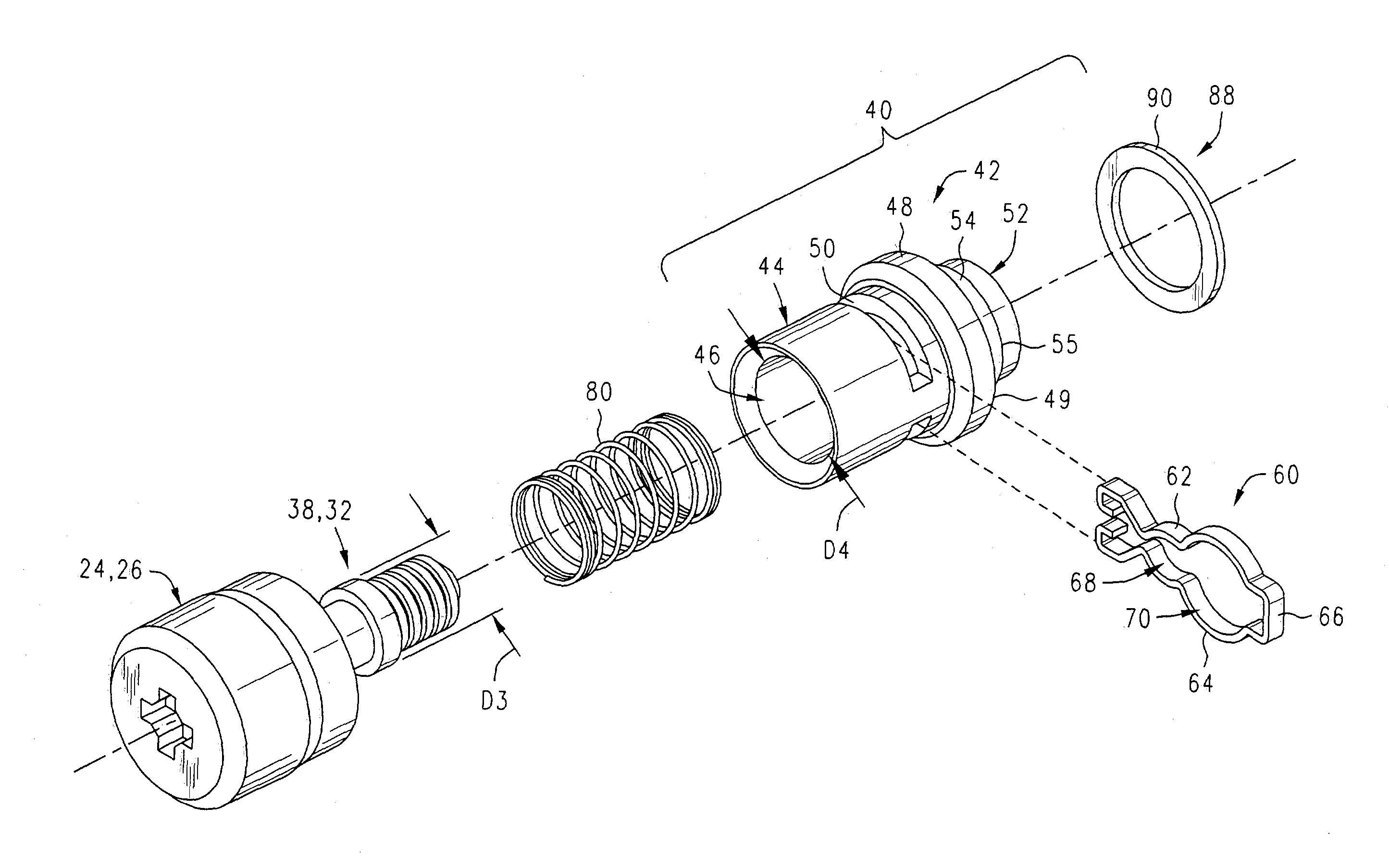
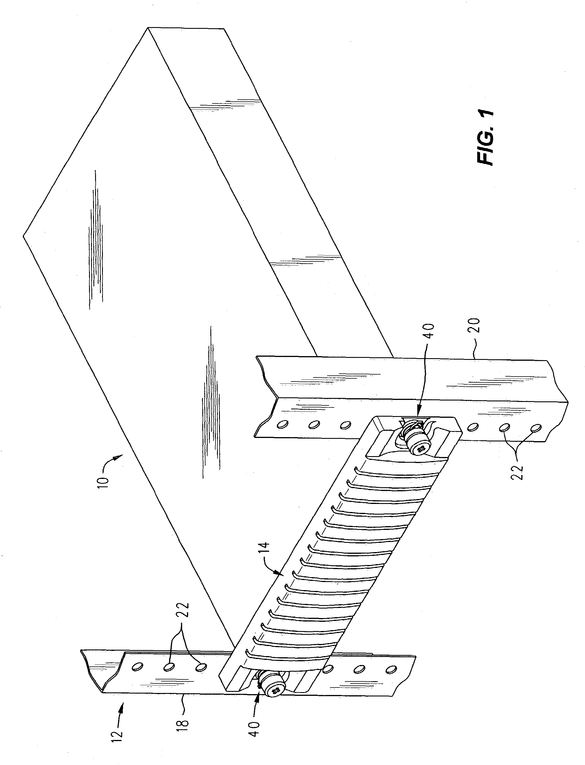
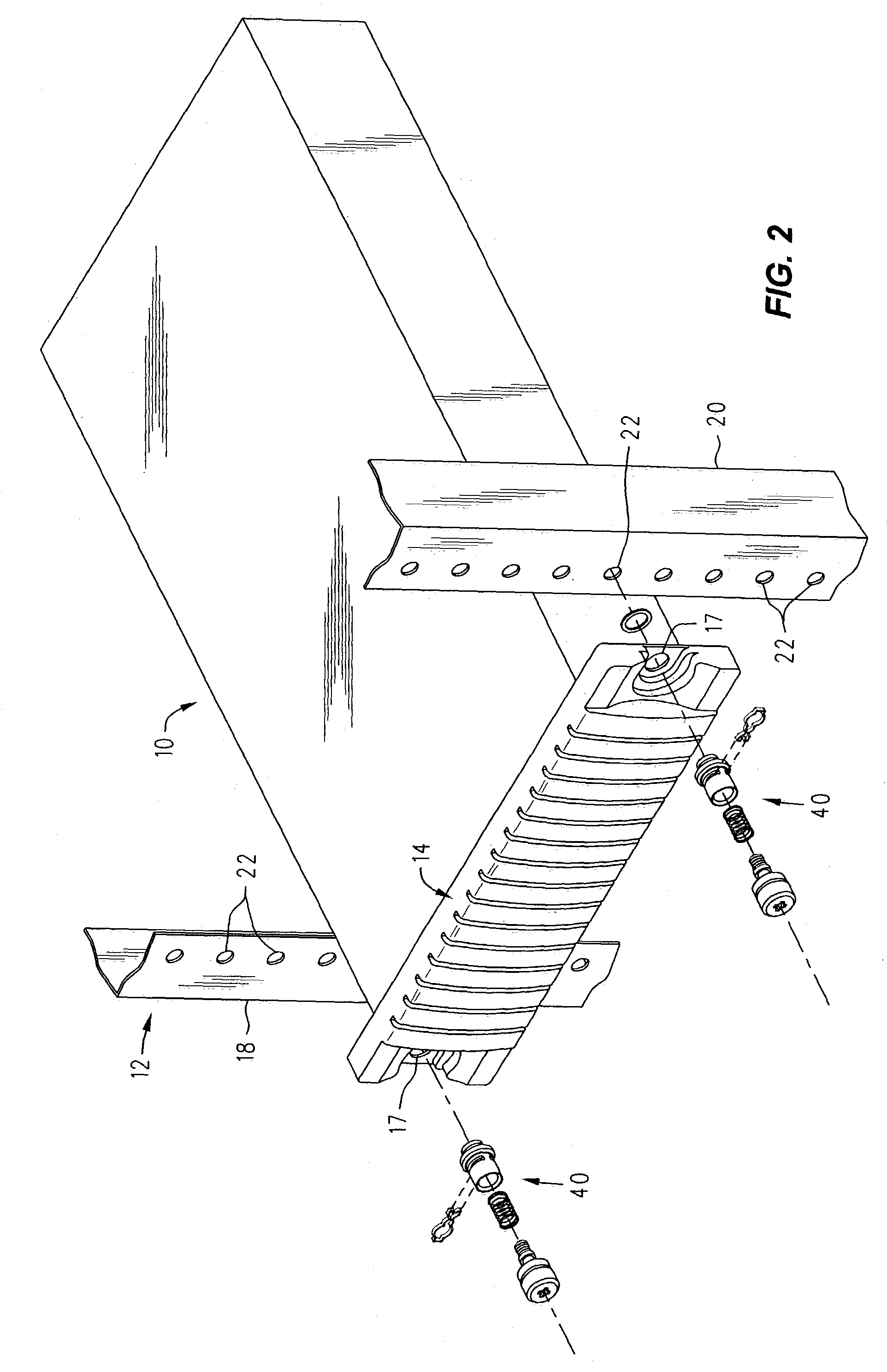
[0017]FIGS. 1 and 2 illustrate an exemplary electronic unit 10 installed in an equipment rack 12 utilizing mounting devices 40 of an embodiment of the invention. The electronic unit 10 may be any type of device such as, for example, a media storage or read / write device, networking device, telephone communications device, or any other device that may be inserted into an equipment rack. The electronic device 10 may have a front panel 14 having a front surface 15, a rear surface 16, and openings 17 (FIG. 2) therein for receiving the mounting devices 40. The equipment rack 12 may have front mounting columns 18, 20, with a plurality of openings 22 therein. For illustrative purposes, only a portion of the front mounting columns 18, 20 of the equipment rack 12 is shown in FIGS. 1 and 2. As used herein, “equipment rack” is defined as any type of rack that is adapted to receive and hold a plurality of electronic units. An electronic unit 10 may come equipped with a first fastener 24, FIG. 3,...


PUM


Abstract

A mounting device for securing an electronic device to an equipment rack includes a mounting member and a securing device mounted on an end of the mounting member.

Description

FIELD OF THE INVENTION[0001]The invention relates generally to devices used for mounting an electronic unit within an equipment rack, and more particularly to a mounting device which allows a user to interchange fasteners to facilitate installation of the electronic unit within an equipment rack.BACKGROUND OF THE INVENTION[0002]An equipment rack may be adapted to receive and hold many types of electronic units such as, for example, media storage and read / write devices, networking devices, and telephone communications devices. After insertion of an electronic unit into an equipment rack, the electronic unit may be secured to the front panel of the equipment rack with fasteners such as screws and, more particularly, thumbscrews. An electronic unit to be installed into an equipment rack may be provided with such fasteners. However, the fasteners on the electronic unit may be incompatible with the corresponding openings in the equipment rack. That is, the equipment rack may be adapted t...

Claims


Application Information

Patent Timeline
Patent Type & Authority Patents(United States)
IPC IPC(8): F16B21/00F16B21/18H05K7/14
CPCF16B21/186H05K7/14H05K7/1421
Inventor ALLEN, JOSEPH R.SMITH, KELLY K.MEGASON, GEORGE D.
Owner HEWLETT PACKARD DEV CO LP
Why Eureka
Try Eureka