
Door lock device for a vehicle

a door lock and vehicle technology, applied in the direction of locking applications, mechanical devices, fastening means, etc., can solve the problems of a plate-shaped member on which the guide groove is formed, the arm supporting the pin, and the pin and the engaging portion of the latch may be damaged

Inactive Publication Date: 2005-11-15
AISIN SEIKI KK +1
View PDF5 Cites 36 Cited by
  • Summary
  • Abstract
  • Description
  • Claims
  • Application Information

AI Technical Summary

Benefits of technology

The present invention is a door lock device for a vehicle that includes a latch and an actuator. The latch can rotate between an open position and a lock position. The actuator can move the latch to the lock position. The drive mechanism includes a guide wall face and a biasing member that presses the operating portion against the guide wall face. The operating portion can be separated from the guide wall face by an external force greater than the biasing force of the biasing member. The technical effect of this invention is to provide a door lock device for a vehicle that ensures secure locking and unlocking of the vehicle door.

Problems solved by technology

Therefore, if the rotating member is driven to rotate in a state in which an obstacle is positioned on the guide groove (for example the engaging projection of the latch is slightly positioned within the guide groove), the pin cannot avoid hitting against a tip portion of the engaging projection of the latch, thereby causing interference between the pin and the engaging portion of the latch.
As a result, any of the arm supporting the pin, the lever rotatably supporting the arm, and a plate-shaped member on which the guide groove is formed may be damaged.

Method used


Image

  • Door lock device for a vehicle
  • Door lock device for a vehicle
  • Door lock device for a vehicle

Examples


Embodiment Construction

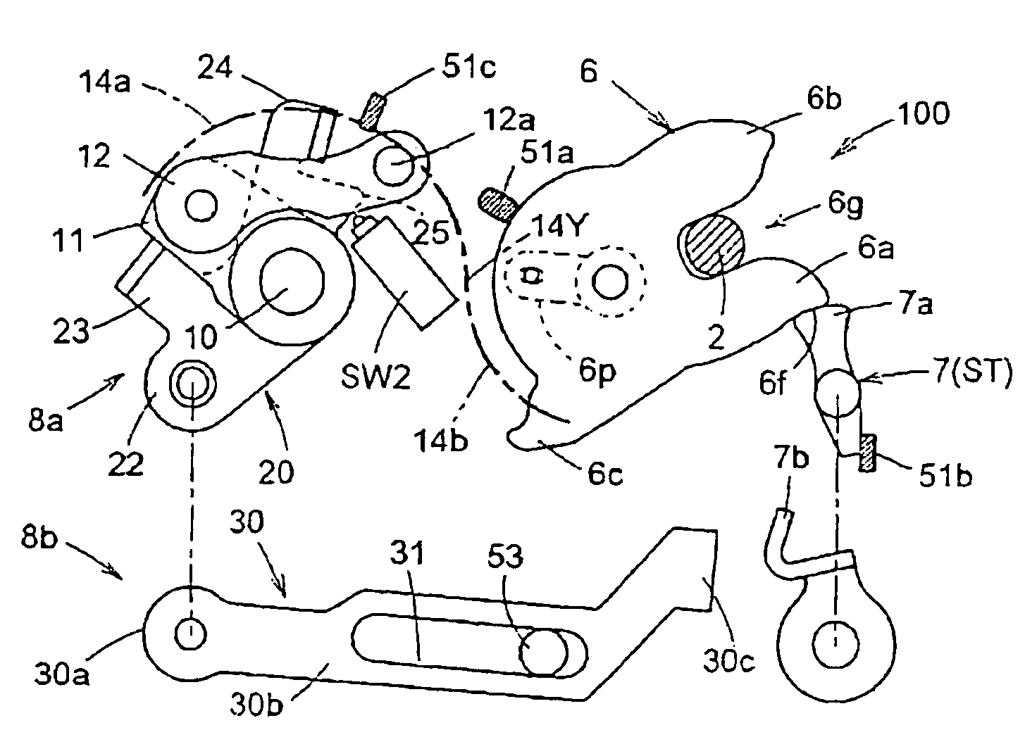
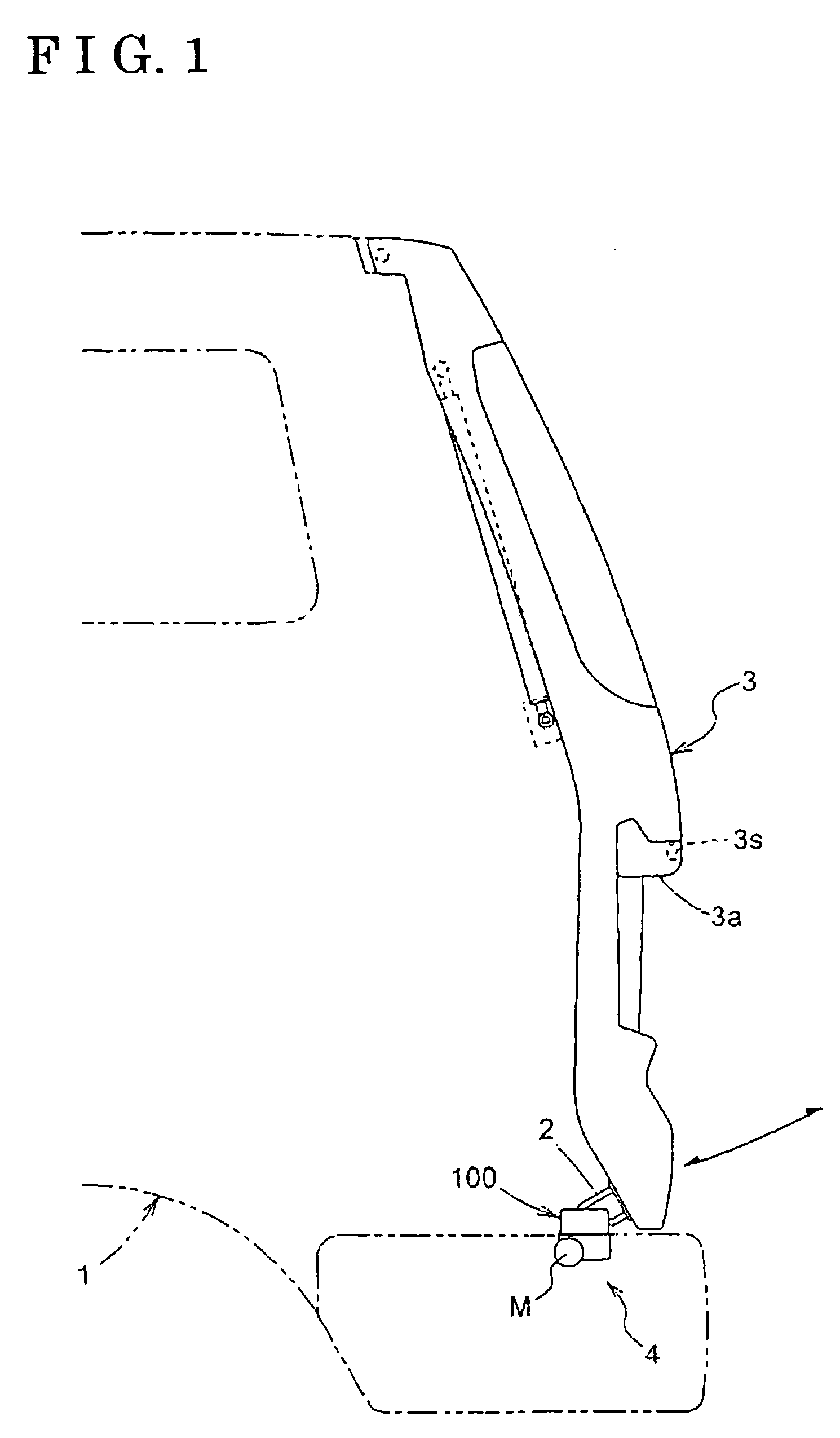
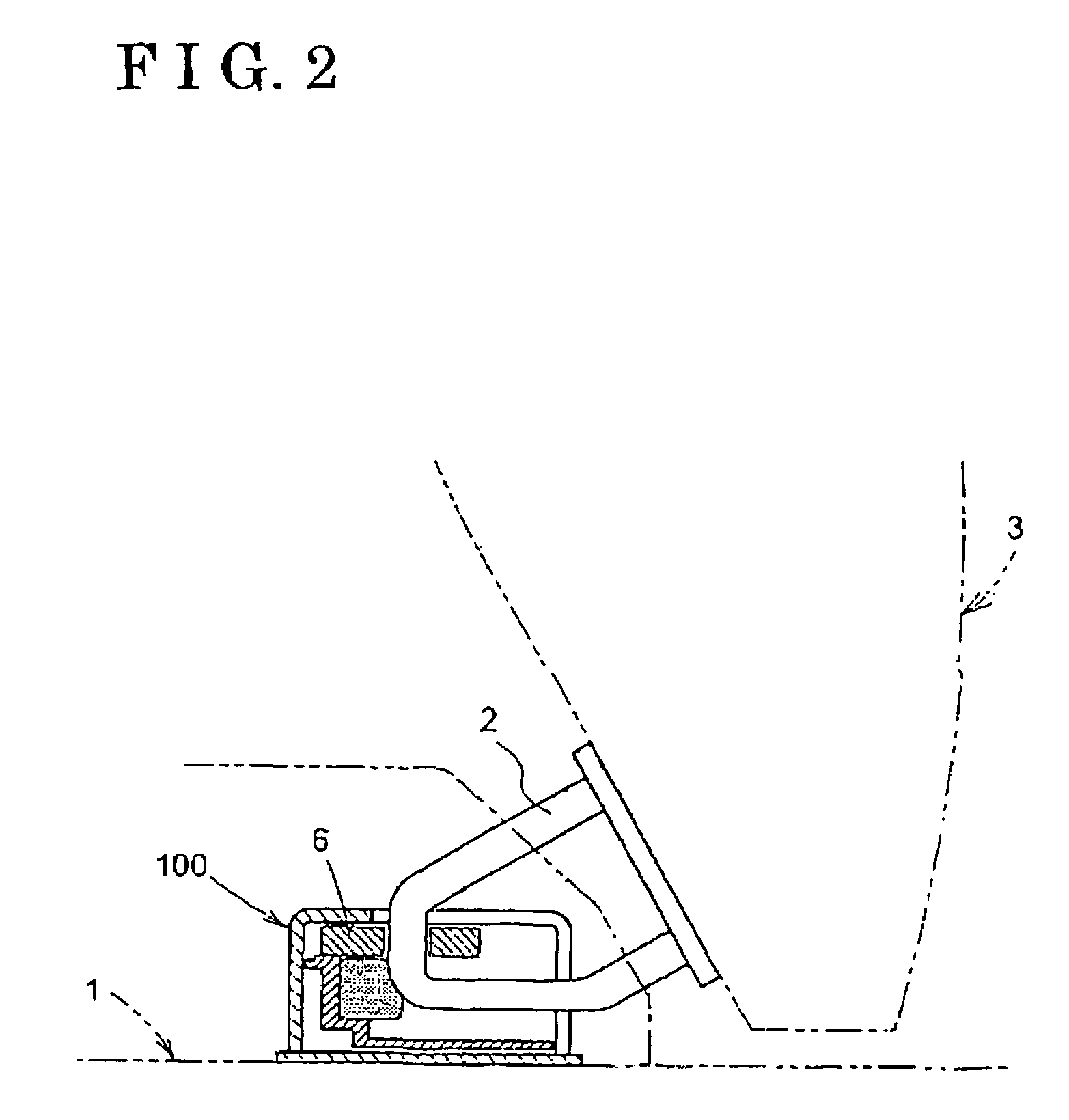
[0023]An embodiment of the present invention is explained referring to attached drawings. FIGS. 1 and 2 show a door opening / closing mechanism 100 disposed between a body 1 and a door 3 (back door in the present embodiment) of a vehicle. The door opening / closing mechanism 100 includes a striker 2 provided at the door 3 and a door lock device 4 provided in the vicinity of a rear edge portion of a floor of the body 1 as shown in FIG. 1. An open handle 3a is provided at an outboard side of the door 3. As shown in FIG. 3, the door lock device 4 includes a synthetic-resin housing 5, a plate-shaped latch 6 that can pull the striker 2 into the body 1 side, a pawl 7 for restricting a rotation of the latch 6, and a lock operation mechanism 8 (actuator) for locking or unlocking the door 3 via a motor-powered operation of the latch 6 and the pawl 7. The housing 5 includes a housing body 5a and a base 5b for covering the housing body 5a from an upper side of the vehicle as shown in FIG. 6 in det...


PUM


Abstract

A vehicle door lock device includes a latch being rotatable between an open position in which the latch is disengageable from a strikes and a lock position in which the latch is prohibited to disengage from the striker, and an actuator for rotating the latch toward the lock position and including an operating portion engageable with an operated portion formed at the latch and a drive mechanism for moving the operating portion being in an engaged state with the operated portion along a predetermined path. The drive mechanism. includes a guide wall face arranged so as to face the operating portion and a biasing member for biasing the operating portion to be pressed against the guide wall face. The operating portion can be separated from the guide wall face by an external force greater than a biasing force of the biasing member.

Description

[0001]This application is based on and claims priority under 35 U.S.C. § 119 with respect to Japanese Application No. 2003-039999 filed on Feb. 18, 2003, the entire contents of which are incorporated herein by reference.FIELD OF THE INVENTION[0002]The present invention generally relates to a door lock device of a vehicle.BACKGROUND OF THE INVENTION[0003]A known vehicle door lock device is disclosed in U.S. Pat. No. 5,520,425. According to an power closing door latch device disclosed in the above patent, the actuator for rotating a latch toward a lock position includes a pin (operating portion) engageable with an engaging projection (operated portion) formed on the latch and a drive mechanism for shifting the pin in an engaged state with the engaging projection along a predetermined path. The drive mechanism includes a slit-shaped guide groove for guiding the pin that is operated based on a rotation force of a rotating member via an arm and a lever to a fully locked position of the l...

Claims


Application Information

Patent Timeline
Patent Type & Authority Patents(United States)
IPC IPC(8): E05B65/12E05B81/20E05B85/24E05B81/30E05B83/18
CPCE05B81/20E05B81/21Y10T292/1082Y10T292/1047
Inventor KOIKE, TSUNEYUKIMACHIDA, TOSHIOODA, TOSHITSUGUTAKAYANAGI, SHINSUKE
Owner AISIN SEIKI KK
Learn More