Information recording medium, and recording method and reproducing method thereof

a technology of information recording and recording method, which is applied in the field of information recording medium, and a recording method and a reproducing method thereof, can solve the problems of copyright protection of dvd-video disc, inability to fully protect copyright protection, and information related to copyright protection can be read ou

Active Publication Date: 2005-11-15
JVC KENWOOD CORP A CORP OF JAPAN
View PDF2 Cites 18 Cited by
  • Summary
  • Abstract
  • Description
  • Claims
  • Application Information

AI Technical Summary

Benefits of technology

[0013]FIG. 1(a) is a partially enlarged cross sectional view of a resist board of an information recording medium according to a first embodiment of the present invention.
[0015]FIG. 2(a) shows configuration of a data sector, which constitutes a recording information to be recorded on an information recording medium of the present invention.

Problems solved by technology

In a case that a recordable optical disc, which is recorded with contents of a DVD-Video disc in conjunction with an information related to copyright protection by a recording apparatus for a high density disc, is reproduced by a DVD-Video disc reproducing apparatus, there existed a problem such that the information related to copyright protection can be read out and the contents of the DVD-Video disc being prohibited to copy can be reproduced.
Accordingly, copyright protection of a DVD-Video disc, which is prohibited to copy, can not be fully protected.

Method used


Image

  • Information recording medium, and recording method and reproducing method thereof
  • Information recording medium, and recording method and reproducing method thereof
  • Information recording medium, and recording method and reproducing method thereof

Examples


first embodiment

[First Embodiment]

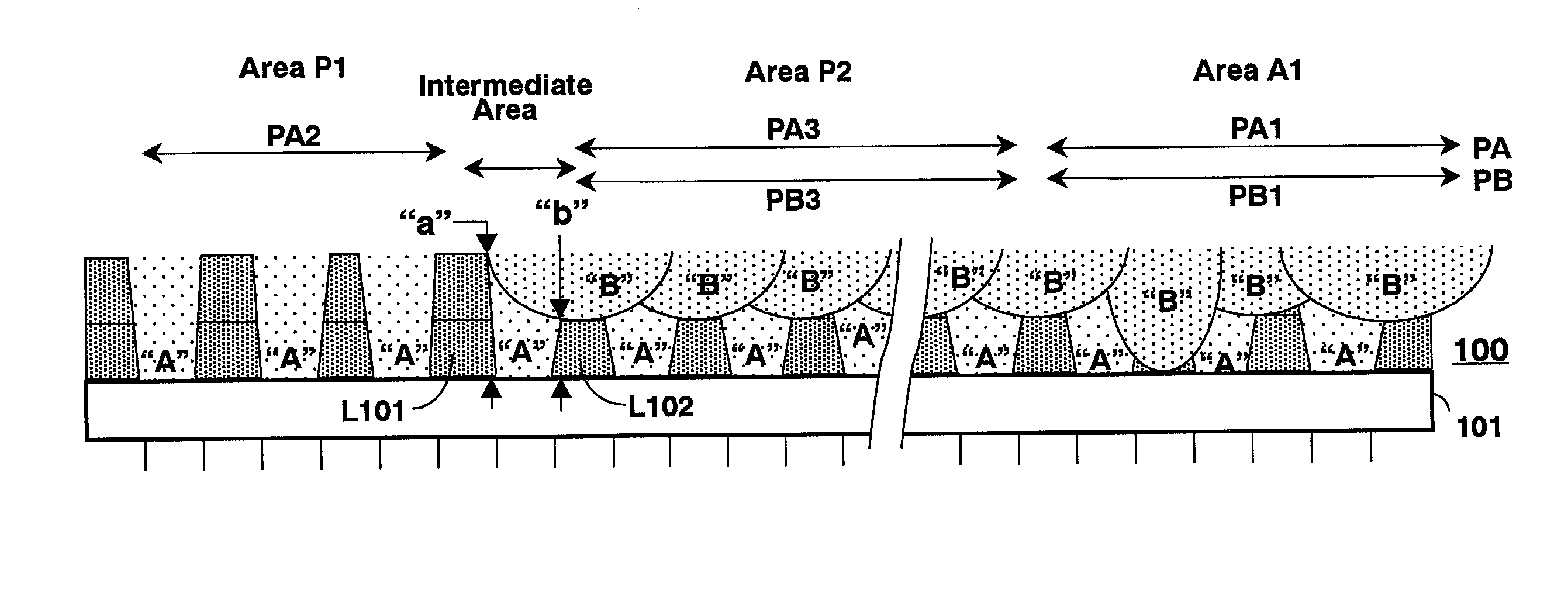
[0084]According to a first embodiment of the present invention, there is provided a recordable optical disc as an information recording medium. The recordable optical disc is designed such that a groove depth of a guide groove and a pit depth of a pit array is different from each other by exposing resist of a guide groove, and that bottoms of a guide groove and a pit array are formed by a top surface of a glass substrate. Further, in a transitional area from a pit array to a guide groove or vise versa, an intermediate area, wherein a height of a guide groove is changed, is provided by changing an output of a laser beam for exposing resist. A tracking error signal in an allowable amplitude difference and a signal within a range of offset level can be obtained by the differential push-pull method and the differential phase detect (DPD) method in the intermediate area.

[0085]By the above-mentioned method, it is confirmed that a pit signal of a pit array adjacent to a g...

second embodiment

[Second Embodiment]

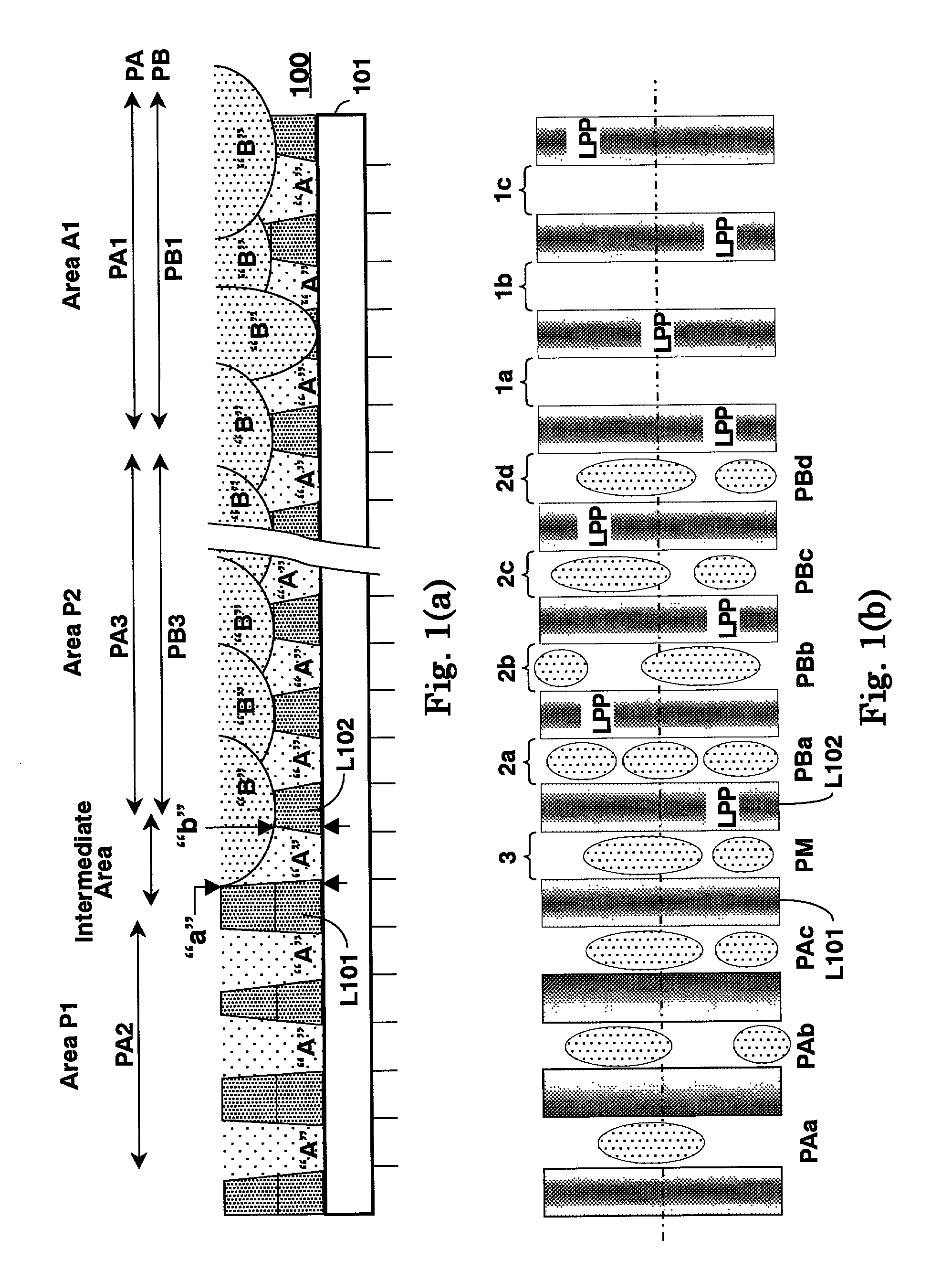
[0146]FIG. 6(a) is a partially enlarged cross sectional view of a resist board of an information recording medium according to a second embodiment of the present invention.

[0147]FIG. 6(b) is a partially enlarged plan view of the resist board shown in FIG. 6(a).

[0148]An information recording medium of the second embodiment is very similar to that of the first embodiment. Therefore, differences from the first embodiment are explained hereto. An information recording medium according to the second embodiment of the present invention is a recordable optical disc having a disc substrate formed with a resist board 200 shown in FIGS. 6(a) and 6(b). In FIG. 6(a), the recordable optical disc is composed of a read only area P201, a recording / reproducing area A201 formed with a guide groove “1” and an intermediate area, which is formed between the areas P201 and A201.

[0149]As shown in FIGS. 6(a) and 6(b), bottoms of pit arrays PAa through PAc (hereinafter generically referre...

third embodiment

[Third Embodiment]

[0151]FIG. 10 shows a configuration of a lead-in area and a data area of an information recording medium according to a third embodiment of the present invention.

[0152]A major difference between FIG. 5 and FIG. 10 is such that the “buffer zone 1” of the type 2 shown in FIG. 5 is referred to an “unreadable emboss with LPP boundary flag 1” area in FIG. 10. In this case, a wobble signal is recorded in all areas and the wobble signal can be obtained from all the areas. This type of disc is defined as a type 3. With respect to recording and reproducing operations of a type 3 disc, the operations of recording and reproducing are shown by a “Write Mode” and a “Read Mode” respectively in the right side of FIG. 10. These operations of the type 3 is a same as those of the type 2 except for the “unreadable emboss with LPP boundary flag 1” area. Therefore, the same operation as that of the type 2 is omitted from a description of the type 3. A different operation from the type ...


PUM

PropertyMeasurementUnit
depthaaaaaaaaaa
depthaaaaaaaaaa
frequencyaaaaaaaaaa

Abstract

An information recording medium in which bottoms of a guide groove and a pit array formed on a disc substrate are allocated on a same flat plane and shaped in flat. Further, in a transition area from a pit array to a guide groove or from a guide groove to a pit array, the information recording medium is provided with an intermediate area composed of a pit array of which height changes from a height between a bottom and a side of a groove to another height between the bottom and a side of the pit array.

Description

BACKGROUND OF THE INVENTION[0001]1. Field of the Invention[0002]The present invention relates to an information recording medium, and a recording method and a reproducing method thereof, wherein the information recording medium is composed of a recording / reproducing area provided with a guide groove and a groove and a read only area formed with a pit array, and further, the information recording medium is formed with an address information of the recording / reproducing area on a land provided between guide grooves as a land pre-pit (hereinafter referred to LPP), and particularly, relates to an information recording medium enabling to be recorded and reproduced such as a DVD-RW (Digital Versatile Disc for Re-recordable) disc, and a recording method and a reproducing method thereof.[0003]2. Description of the Related Art[0004]Generally, in a high density recordable optical disc (hereinafter abbreviated as a recordable optical disc) such as a DVD-RW disc, which is interchangeable with a...

Claims


Application Information

Patent Timeline
Patent Type & Authority Patents(United States)
IPC IPC(8): G11B27/30G11B27/19G11B7/013G11B7/26G11B27/24G11B20/12G11B7/09G11B7/007G11B7/24076G11B7/24079G11B7/24082G11B7/24085G11B21/08
CPCG11B7/0053G11B7/007G11B7/00718G11B7/00736G11B7/00745G11B7/0079G11B7/0901G11B7/0938G11B7/24079G11B7/24085G11B7/261G11B19/122G11B20/00086G11B20/00115G11B20/00594G11B20/00695G11B20/1217G11B27/24G11B27/3027G11B7/0904G11B7/24076G11B7/24082G11B2020/1238G11B2020/1239G11B2020/1268G11B2020/1274G11B2220/216G11B2220/2562G11B2220/2566
Inventor UEKI, YASUHIRO
Owner JVC KENWOOD CORP A CORP OF JAPAN
Why Eureka
Try Eureka