Clock forward initialization and reset signaling technique

Inactive Publication Date: 2005-12-13
VALTRUS INNOVATIONS LTD +1
View PDF14 Cites 9 Cited by
  • Summary
  • Abstract
  • Description
  • Claims
  • Application Information

AI Technical Summary

Benefits of technology

[0025]Advantageously, the present invention provides a means for initializing a PLL-based clocking system without the use of special signals and control mechanisms. Prior attempts to initialize such a subsystem involved a system global reset signal means and / or a local reset signaling means operating independently of the unit to be reset. The present invention provides a simpler solution that requires no external reset mechanism and that self-initializes the PLL, initializes the I / O interface and retains critical error state despite the loss and subsequent restart of the forwarded clock signals. In addition, the initialization / reset logic circuit reduces part counts and enables an inexpensive implementation.

Problems solved by technology

In certain cases, clock signals received from the processor may be stopped intentionally or due to errors or failures; as a result, communication between the processor and the ASIC is no longer possible.
Consequently, the PLL no longer operates correctly, if at all, and requires execution of the initialization sequence described above.

Method used


Image

  • Clock forward initialization and reset signaling technique
  • Clock forward initialization and reset signaling technique
  • Clock forward initialization and reset signaling technique

Examples


Embodiment Construction

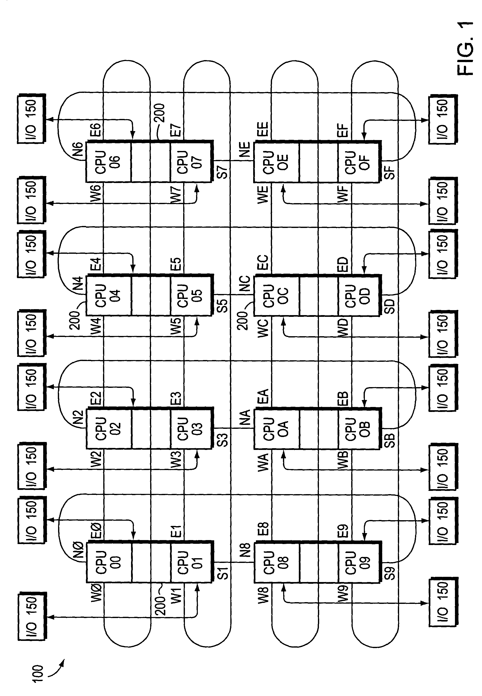
[0033]FIG. 1 is a schematic block diagram of a data processing system 100 that may be advantageously used with the present invention. In the illustrative embodiment, the data processing system is preferably a symmetrical multiprocessor (SMP) system 100 comprising a plurality of processor modules 200 interconnected to form a two dimensional (2D)-torus mesh configuration. Each processor module 200 comprises two central processing units (CPUs) with connections for two input / output (I / O) ports along with 6 inter-processor (IP) network ports. The network ports are preferably referred to as North (N), South (S), East (E) and West (W) compass points, wherein the North-South (NS) and East-West (EW) compass point connections create a (manhattan) grid. Additionally, the outside ends of the mesh wrap-around and connect to each other. I / O traffic enters the 2D torus via I / O channel connections between the CPUs and I / O subsystem 150. Each compass point is coupled to an IP channel that comprises ...


PUM


Abstract

A system and method for initializing and resetting a clocking subsystem having a phased locked loop (PLL) within an input / output interface of a data processing system. A first timer generates signals in response to receiving clock signals from a clock source. A second timer detects the presence or absence of signals from the first timer and in response to an absence outputs a circuit reset signal to a circuit. The circuit in turn issues a reset signal to the PLL and to other systems.

Description

CONTINUATION CASE[0001]The present application is a continuation of commonly assigned and U.S. patent application Ser. No. 09 / 652,980 filed on Aug. 31, 2000 now U.S. Pat. No. 6,629,257 and has the same title and inventors as the present application. This prior application is incorporated herein by reference, and priority is claimed therefrom under 35 U.S.C. §120.INCORPORATION BY REFERENCE OF RELATED APPLICATIONS[0002]The present application is related to the following co-pending, commonly owned U.S. Patent Applications, all of which were filed on even date with the parent of the present continuation application for United States Patent and are each hereby incorporated by reference in their entirety:[0003]U.S. patent application Ser. No. 09 / 652,644 filed on Aug. 31, 2000, entitled ADAPTIVE DATA PREFETCH PREDICTION ALGORITHM;[0004]U.S. patent application Ser. No. 09 / 653,133 filed on Aug. 31, 2000, now issued as U.S. Pat. No. 6,456,510 on Sep. 24, 2002 entitled UNIQUE METHOD OF REDUCIN...

Claims


Application Information

Patent Timeline
IPC IPC(8): G06F1/24
CPCG06F1/24
Inventor HARTWELL, DAVID
Owner VALTRUS INNOVATIONS LTD
Why Eureka
Try Eureka