Contact lens mold

a contact lens and mold technology, applied in the field of contact lens molds, can solve problems such as eye discomfort and/or eyelid discomfor

Inactive Publication Date: 2006-02-14
ALCON INC
View PDF13 Cites 95 Cited by
  • Summary
  • Abstract
  • Description
  • Claims
  • Application Information

AI Technical Summary

Benefits of technology

[0012]These objects are achieved by an ophthalmic lens mold having a first mold half having a front side and a back side and a second mold half having a front side. The front side of each of the first and second mold halves defines an optical surface. Upon alignment of the first mold half with respect to the second mold half so that the front sides oppose each other, a mold cavity is formed between the front sides to form a contact lens therein from a moldable material, so that the optical surfaces form respective opposing optical surfaces of the ophthalmic lens. The first mold half includes a first section that transmits curing light and that extends from the back side to the front side. The first section includes at least an area of the first mold half optical surface enclosed by an outermost circumference of the ophthalmic lens. A second section is co-molded with the first section and blocks the light. The second section is disposed with respect to the first section so that the second section prevents curing light incident to the back side from passing through the first mold half into the area of the mold cavity extending from the first mold half front side to the second mold half front side surrounding and extending radially outward' of a boundary that includes the ophthalmic lens circumference and so that the first section passes the incident light to an area of the mold cavity bounded by and within the boundary.

Problems solved by technology

The circumferential edge of an ophthalmic lens, e.g., contact lens or intraocular lens, is critical in that irregularities in this edge can cause discomfort to the eye and / or to the eyelid as it passes over the edge.

Method used


Image

  • Contact lens mold
  • Contact lens mold
  • Contact lens mold

Examples


Embodiment Construction

[0031]Reference will now be made in detail to presently preferred embodiments of the invention, one or more examples of which are illustrated in the accompanying drawings. Each example is provided by way of explanation of the invention, not limitation of the invention. In fact, it will be apparent to those skilled in the art that modifications and variations can be made in the present invention without departing from the scope or spirit thereof. For instance, features illustrated or described as part of one embodiment may be used on another embodiment to yield a still further embodiment. Thus, it is intended that the present invention covers such modifications and variations as come within the scope of the appended claims and their equivalents.

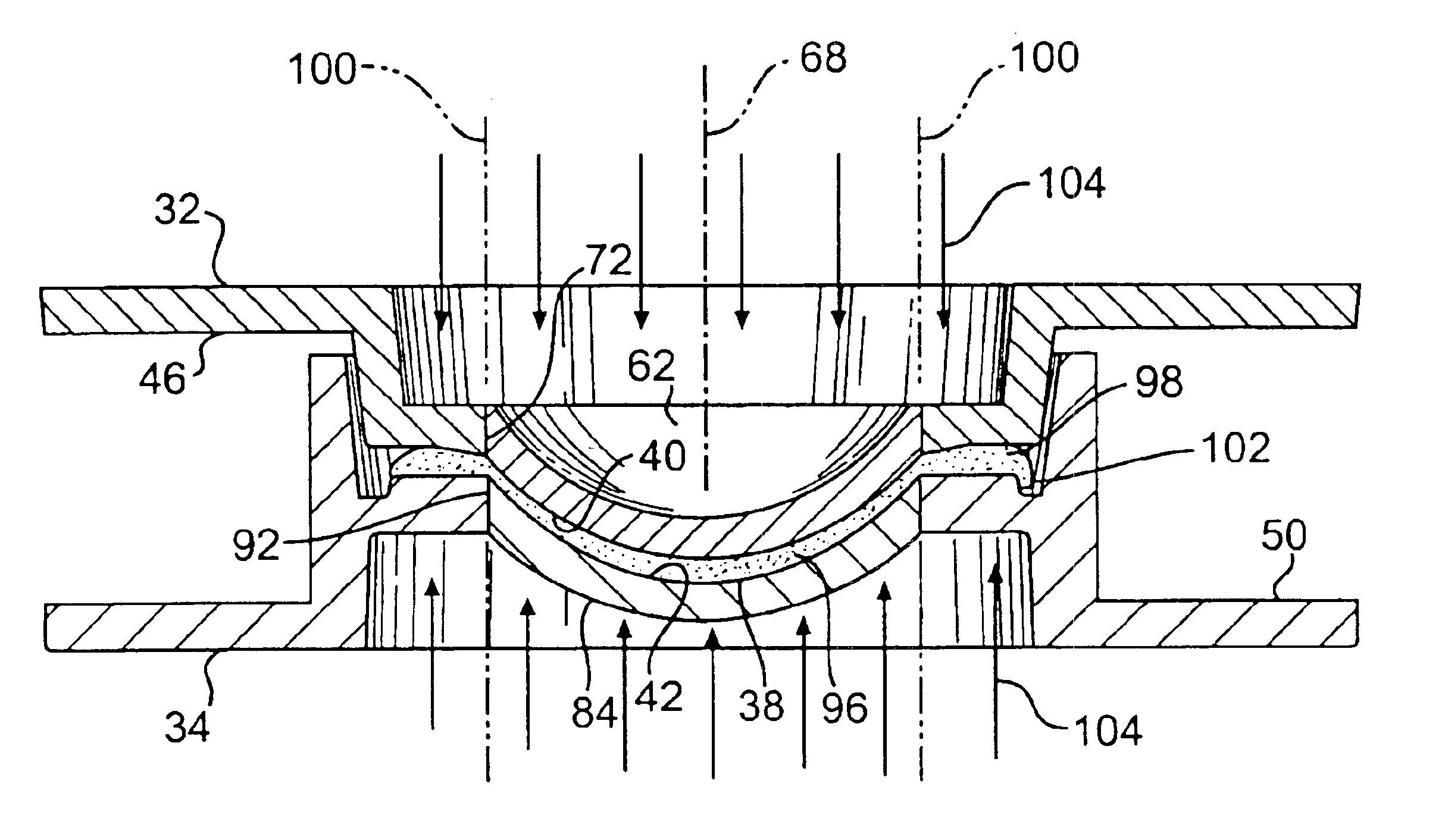
[0032]Referring to FIG. 3 a contact lens mold 30 includes a back (or “base”) curve mold half 32 and a front curve mold half 34 which may be brought together as indicated by arrow 36 to form a mold cavity 38 (FIG. 8) between optical surfaces 40...


PUM

PropertyMeasurementUnit
areaaaaaaaaaaa
thicknessaaaaaaaaaa
opticalaaaaaaaaaa

Abstract

An ophthalmic lens mold includes a first mold half having a front side and a back side. The front side defines an optical surface. A second mold half has a front side defining an optical surface. Upon alignment of the first mold half with respect to the second mold half so that the front sides oppose each other, a mold cavity is formed between the front sides to form an ophthalmic lens therein from a moldable material. The first mold half includes a first section that transmits curing light and that extends from the back side to the front side. The first section includes at an area of the first mold half optical surface enclosed by an outermost circumference of the ophthalmic lens. A second section is co-molded with the first section and blocks the light. The second section is disposed with respect to the first section so that the second section prevents the curing light incident to the-back side from passing through the first mold half into an area of the mold cavity extending from the first mold half front side to the second mold half front side surrounding and extending radially outward of a boundary that includes the ophthalmic lens circumference and so that the first section passes the incident light to an area of the mold cavity bounded by and within the boundary.

Description

[0001]This application claims priority of the provisional patent application No. 60 / 198,132 having a priority date of Mar. 31, 1999, which application was converted to a provisional application by petition, based on non-provisional application Ser. No. 09 / 282,915, filed Mar. 31, 1999.BACKGROUND OF THE INVENTION[0002]The present invention is directed to an ophthalmic lens mold. More specifically, the invention is directed to an improved ophthalmic lens mold.[0003]The circumferential edge of an ophthalmic lens, e.g., contact lens or intraocular lens, is critical in that irregularities in this edge can cause discomfort to the eye and / or to the eyelid as it passes over the edge. It is also important that the edge create a smooth transition as the eyelid moves from the eye to the lens to prevent unwanted lens movement.[0004]Ophthalmic lenses are often made by cast molding, in which a monomer material is deposited in a cavity defined between optical surfaces of opposing halves of a lens m...

Claims


Application Information

Patent Timeline
Patent Type & Authority Patents(United States)
IPC IPC(8): B29D11/00
CPCB29D11/00432Y10S425/808B29D11/00509
Inventor ANDINO, RAFAEL VICTORTAPALE, MAYURESH SHASHIKANTBROOKS, CHRISTOPHER JOHNSTOECKMAN, WALTER RAYVANROYEN, DONALD FRASER
Owner ALCON INC
Why Eureka
Try Eureka