Method and system for preventing vehicle thefts

a technology for preventing vehicle theft and preventing theft, applied in the field of vehicle theft, can solve the problems of limiting the places in which thieves can be hidden, offering little or no deterrent, and still on the rise of vehicle th

Inactive Publication Date: 2006-05-23
TAG TRACKING INC
View PDF23 Cites 40 Cited by
  • Summary
  • Abstract
  • Description
  • Claims
  • Application Information

AI Technical Summary

Benefits of technology

[0008]Another object of the present invention is to deter thieves from stealing vehicles.
[0009]Yet another object of the present invention is to provide a system that will be advantageous for all parties involved in the vehicle industry.

Problems solved by technology

Even with the advent of several new technologies in the vehicle tracking and theft prevention arena, vehicle theft is still on the rise.
The overwhelming majorities of conventional anti-theft devices are easily removable or bypassed and thus offer little or no deterrence to a thief.
Tracking systems are all “hard wired” to the vehicle in which they are installed thus limiting the places in which they can be hidden and making them vulnerable to being discovered, deactivated and or removed.
Also, because they rely on radio frequencies and operate using 2-way communication they can easily be detected and “jammed”, or rendered inoperable with well-known devices such as frequency jammers.
Furthermore, as electrical systems found in vehicles become increasingly complex and sensitive, consumers and vehicle manufactures are becoming increasingly weary of these “hard wired” systems due to the fact that their interaction with the vehicle circuits can cause several mal functions.
In some cases the installation of “hard wired” systems can even void certain vehicle manufacturer warranties.
As for traditional transponder systems they operate at very limited ranges and can only be used in a very specific area such as a room or doorway.

Method used


Image

  • Method and system for preventing vehicle thefts
  • Method and system for preventing vehicle thefts
  • Method and system for preventing vehicle thefts

Examples


Embodiment Construction

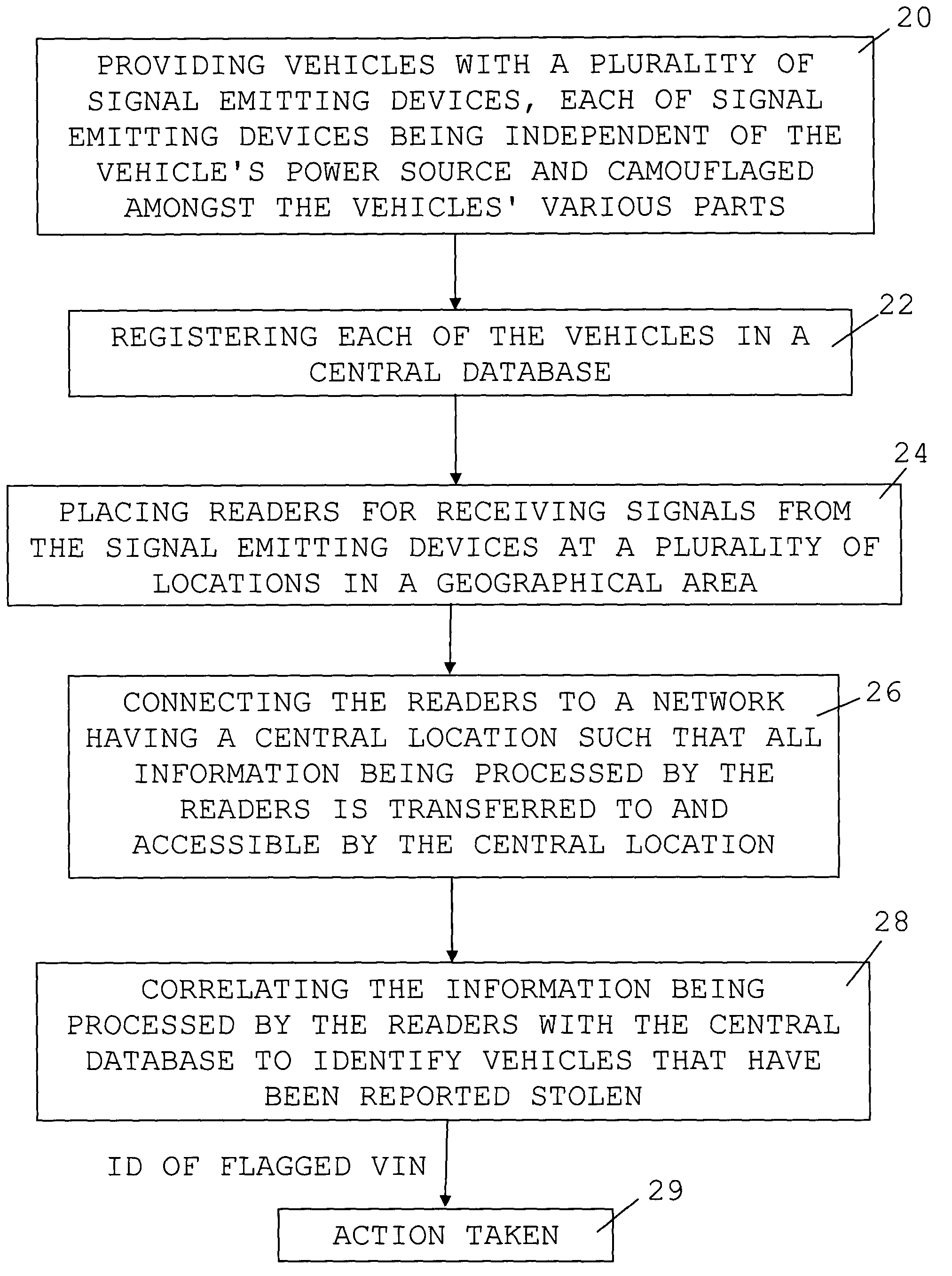
[0020]Throughout this application, the preferred embodiment of the present invention will be referred to as a “TAG” system. A TAG is to be understood as a signal emitting device that is placed within various parts of a vehicle. The signal is emitted for the purpose of transmitting information to a receiving entity. In one embodiment, the TAGs emit signals at regular or irregular intervals without being prompted to do so. In another embodiment, the TAGs will emit signals as a result of having received a prompt from either a TAG reader or the network with which the system works. It is also possible to have TAGs that emit signals without the prompt, but can also receive a request from a TAG reader or the network to emit at a particular point in time and emit in response to that request.

[0021]Unlike conventional anti-theft devices, the TAG system is virtually impossible to completely remove or bypass. The TAGs are stand-alone and do not need to be wired to the vehicle's power source. Th...


PUM


Abstract

There is described a system for preventing vehicle theft, the system comprising: a plurality of signal emitting devices placed and camouflaged among various parts of a vehicle, each of the plurality of signal emitting devices being independent of the vehicle's power source; readers placed at a plurality of locations in a geographical area and connected to a network having a central location, the readers receiving signals from the plurality of signal emitting devices and transferring reader data to the central location; and a central database at the central location comprising registration data for each vehicle equipped with the signal emitting devices, and whereby the central database is correlated with the reader data to identify vehicles that have been stolen.

Description

FIELD OF THE INVENTION[0001]The invention relates to the field of vehicle theft. More specifically, it relates to a method and system for dissuading vehicle thieves from stealing a vehicle and encouraging vehicle owners to adopt the method and system.BACKGROUND OF THE INVENTION[0002]Even with the advent of several new technologies in the vehicle tracking and theft prevention arena, vehicle theft is still on the rise. Vehicle tracking does not stop the theft from occurring nor does it serve as a major deterrent. The overwhelming majorities of conventional anti-theft devices are easily removable or bypassed and thus offer little or no deterrence to a thief.[0003]Tracking systems are all “hard wired” to the vehicle in which they are installed thus limiting the places in which they can be hidden and making them vulnerable to being discovered, deactivated and or removed. Also, because they rely on radio frequencies and operate using 2-way communication they can easily be detected and “ja...

Claims


Application Information

Patent Timeline
Patent Type & Authority Patents(United States)
IPC IPC(8): B60R25/10
CPCB60R25/1025G06Q40/08B60R25/33
Inventor GALLOVICH, JASON
Owner TAG TRACKING INC
Why Eureka
Try Eureka