Self-regenerative xerographic coatings

a xerographic coating and self-regenerative technology, applied in the field of self-regenerative, polymeric coatings, can solve the problems of reducing the likelihood of parking deletion, image ghosting, photoreceptor cracking, etc., and achieve the effect of increasing the life and effectiveness of the catalytic surfa

Inactive Publication Date: 2006-05-23
XEROX CORP
View PDF22 Cites 10 Cited by
  • Summary
  • Abstract
  • Description
  • Claims
  • Application Information

AI Technical Summary

Benefits of technology

[0016]The invention is directed to methods for increasing the life and effectiveness of catalytic surfaces, such as charging device surfaces, by neutralizing ozone and nitrogen oxide species. Such neutralization reduces the likelihood of parking deletions, image ghosting, photoreceptor cracking, doner / fuser roll filming, and other xerography-related problems.
[0018]In accordance with a further aspect of the invention, a charging device surface is coated with a substantially continuous, thin, conductive, dry film comprising powdered active component to neutralize the nitrogen oxide species when they are generated. The coating further comprises a binder, preferably, a styrene acrylate copolymer combined with a silicone oil, which permits the coating to expose fresh active component, thus providing continuous neutralization of the ozone and nitrogen oxide species. The coating protects the charging device, an electrode wire housed within the charging device assembly, and the environment surrounding the charging device from wire generated ozone and nitrogen oxide species.

Problems solved by technology

Such neutralization reduces the likelihood of parking deletions, image ghosting, photoreceptor cracking, doner / fuser roll filming, and other xerography-related problems.

Method used


Image

  • Self-regenerative xerographic coatings
  • Self-regenerative xerographic coatings
  • Self-regenerative xerographic coatings

Examples


example 1

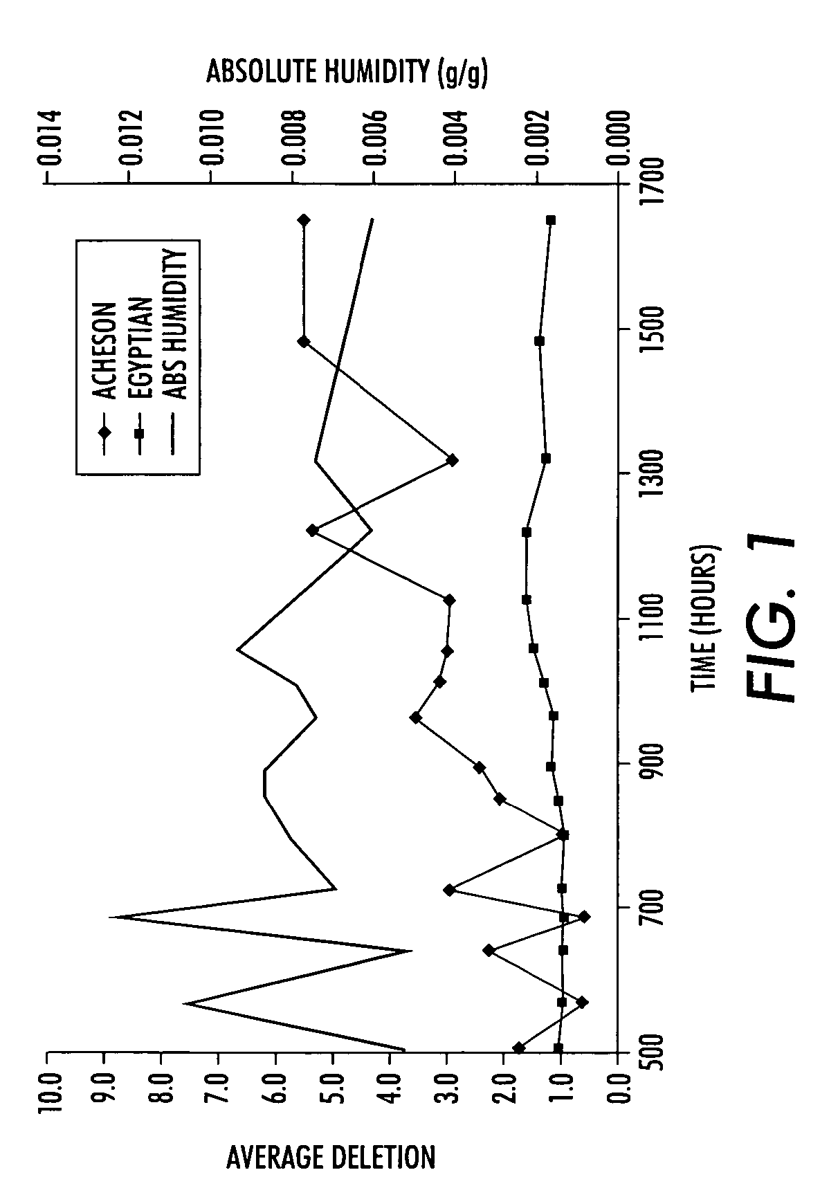
Outgassing Performance / Parking Deletion Tests

[0046]Test 1

[0047]Egyptian Lacquers DAG MQW-L120 (Egyptian Lacquers Mfg. Co.) (water-based coating comprising a nickel active component in a styrene acrylate copolymer and polydimethylsiloxane binder with a surfynol defoamer, aluminum hydroxide, alkali silicate, and graphite) was compared to Acheson Colloids (Acheson Colloids Co., Port Huron, Mich.) DAG JD29080 (water-based coating comprising a nickel active component in an acrylic binder of a polyvinylacetate and polybutylacrylate blend and further comprising aluminum hydroxide, alkali silicate, and graphite), and to Acheson Colloids RW22932 DAG (water-based coating comprising a non-nickel active component in an acrylic binder of a polyacrylic acid and polyacrylamide blend and further comprising aluminum hydroxide, sodium silicate, and graphite).

[0048]The Egyptian Lacquers and Acheson Colloids materials were coated onto substrates of beryllium copper (BeCu), aluminum (Al), and 400 series...

example 2

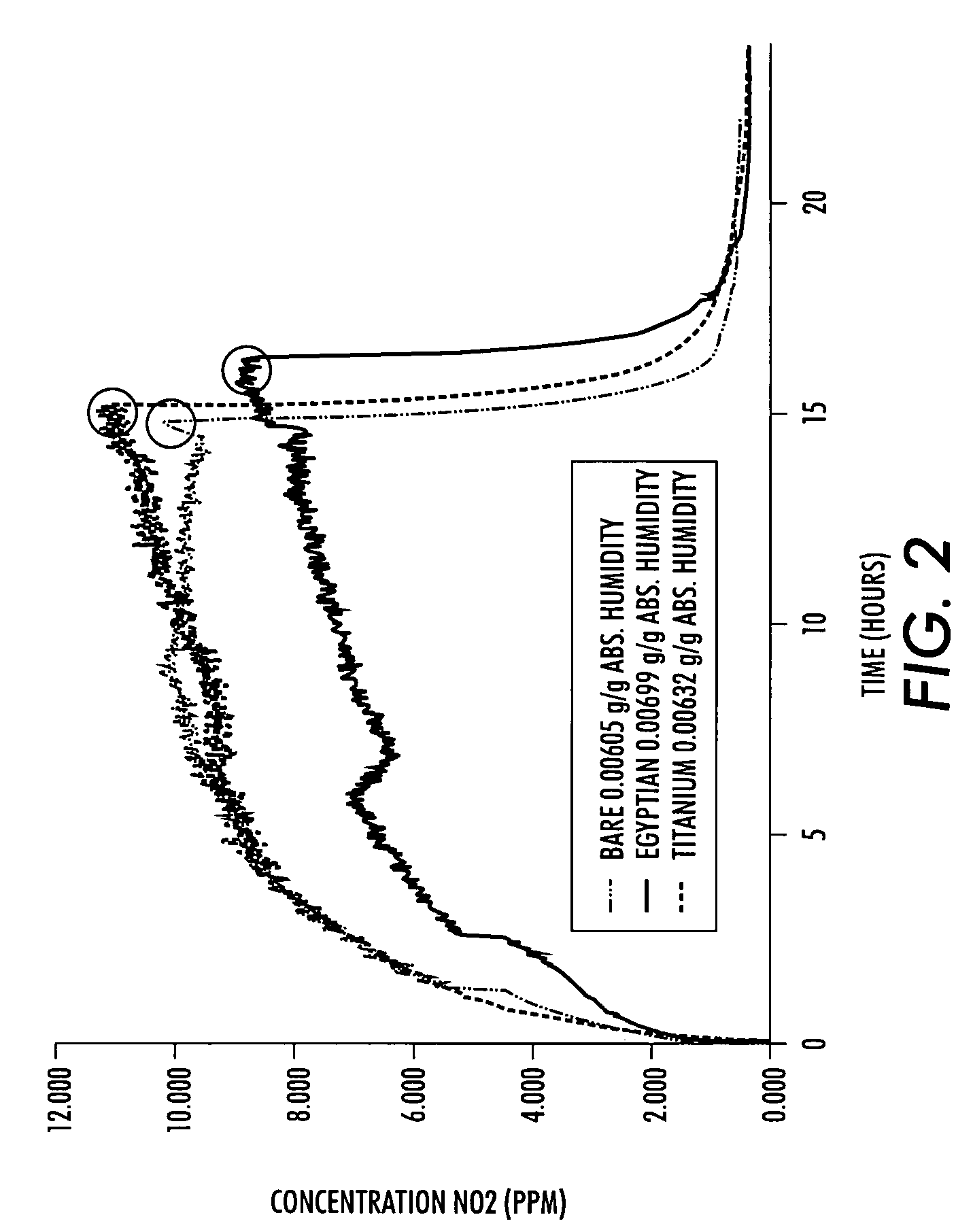
Nitric Acid Reduction

[0059]The Egyptian Lacquers MQW-L120 coating on an aluminum panel was further tested in a sealed chamber for its effect on nitric oxide concentrations. It was determined using a charging device that such concentrations were reduced by approximately 30% in the sample test chamber. Nitric oxide concentration was measured with a NOx meter (Ecophysics, Ann Arbor, Mich.).

[0060]The operation of the charging device (either pin array negative scorotron or AC dicorotron) produced distinct phases as summarized in FIGS. 8 and 9. As illustrated in FIG. 8, during the initial phase, the NOx meter was run with the dicorotron charging device off. The measured levels are from background NOx concentration found in the environment (ambient NOx is mostly of the NO variety). The build up phase started at the time that the charging device was turned on. At first, the NO2 build up was extremely rapid, then the concentration dropped. The build up then proceeded through a somewhat linea...


PUM


Abstract

The invention is directed to self-regenerative, polymeric coatings and methods of using the coatings in xerography to increase the life and effectiveness of catalytic surfaces, such as, for example, charging device surfaces, by neutralizing ozone and nitrogen oxide species.

Description

BACKGROUND OF THE INVENTION[0001]1. Field of Invention[0002]The invention is directed to self-regenerative, polymeric coatings and methods of using the coatings in xerography to increase the life and effectiveness of catalytic surfaces, such as, for example, charging device surfaces, by neutralizing ozone and nitrogen oxide species.[0003]2. Description of Related Art[0004]In electrophotographic printing, also known as electrophotography or xerography, a photoreceptor containing a photoconductive insulating layer on a conductive layer is imaged by first uniformly electrostatically charging its surface. The photoreceptor is then exposed to a pattern of activating electromagnetic radiation, such as light or a scanning laser beam. The radiation selectively dissipates the charge in the illuminated areas of the photoconductive insulating layer while leaving behind an electrostatic latent image in the non-illuminated areas. This electrostatic latent image may then be developed to form a vi...

Claims


Application Information

Patent Timeline
Patent Type & Authority Patents(United States)
IPC IPC(8): G03G15/02
CPCG03G15/0258Y10S430/102G03G2215/027
Inventor BLAIR, CHRISTOPHER D.DEBIES, THOMAS P.CERRAH, KEN M.WICKETT, ANNE L.TAFT, KEVIN H.BAINES, KRISTEN V.
Owner XEROX CORP
Why Eureka
Try Eureka