Cordless base

a cordless base and power supply technology, applied in the direction of flexible/turnable line connectors, coupling device connections, cooking vessels, etc., can solve the problems of occupying a considerable portion of the area of any working surface, and affecting the work efficiency of the kitchen

Inactive Publication Date: 2006-07-11
KHOURY EDWARD
View PDF54 Cites 46 Cited by
  • Summary
  • Abstract
  • Description
  • Claims
  • Application Information

AI Technical Summary

Problems solved by technology

However they are perforce of substantial size and take up a considerable portion of the area of any working surface on which they stand.
This is a disadvantage in modern kitchens which often have restricted work surfaces.

Method used


Image

  • Cordless base
  • Cordless base
  • Cordless base

Examples


Embodiment Construction

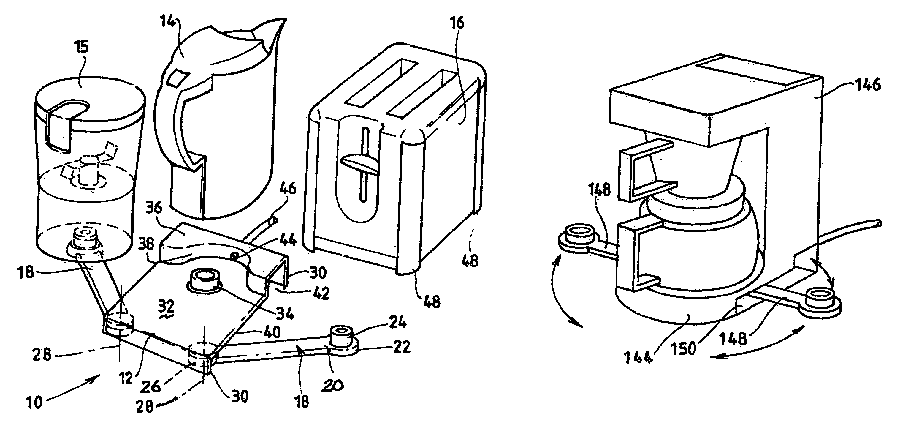
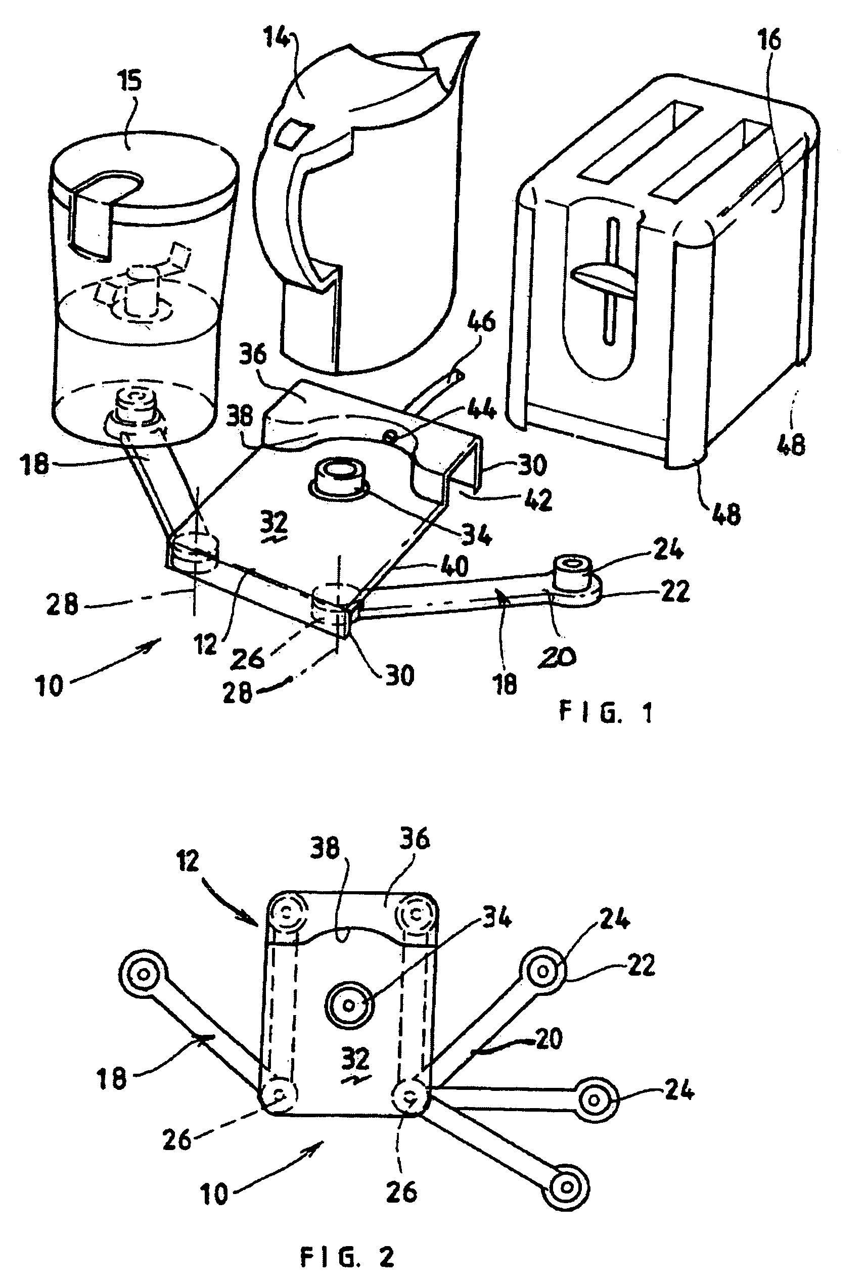
[0021]Referring now to FIGS. 1 and 2 there is shown a modular appliance system comprising a power supply apparatus 10, incorporating a distribution member12, and a set of modular appliances 14, 15 and 16. The distribution member 12 is normally carried on a working surface. It is moulded from a suitably tough and heat resisting plastics material such as polypropylene. The distribution member 12 can be formed from other suitable plastics or other materials including metals such as stainless steel or natural materials such as marble or wood.

[0022]The distribution member 12 has a pair of power supply devices 18 which are attached to it as will be described. Each power supply device 18 comprises an elongated extension arm 20 that is a low flat elongated member of substantially rectangular cross-section. The free end of each arm 20 has a circular end piece 22 to which the arm extends transversely. This end piece 22 has coaxially mounted thereon a vertical cylindrical cordless connector 24...


PUM


Abstract

A modular appliance system comprising a plurality of modular appliances, a base unit for supporting at least two of the modular appliances simultaneously or a free standing unit for supporting one or more modular appliances simultaneously or a free standing appliance for supporting one or more modular appliances simultaneously. Hingedly attached extensions are movable between points under and around the base, free standing unit and free standing appliance. The extensions provide electric power through cordless connectors and may be pivoted, hingedly attached or on slides.

Description

CROSS REFERENCE TO RELATED APPLICATIONS[0001]This application is a continuation of prior U.S. application Ser. No. 10 / 479,261, filed on Apr. 30, 2004, now U.S. Pat. No. 6,843,667, which is a U.S. national phase application of International Application No. PCT / AU01 / 00827, filed on Jul. 10, 2001, and which claims the priority of Australian application number PR5384, filed on Jun. 1, 2001.BACKGROUND OF THE INVENTION[0002]1. Field of the Invention[0003]This invention relates to power supply apparatus for domestic appliances.[0004]2. Description of the Prior Art[0005]The invention is concerned with such apparatus of the kind including a cordless connector for connection to a female connector in an appliance. Known power supply apparatus of this kind comprise a base unit which rests on a working surface and on which the appliance stands when engaging the connector. The base unit is bigger than the appliance and very much larger than the connector. Typical arrangements of this kind are dis...

Claims


Application Information

Patent Timeline
Patent Type & Authority Patents(United States)
IPC IPC(8): H01R13/44H01R13/514H01R24/00H01R25/00H01R35/04
CPCA47J27/2105A47J31/057A47J37/08A47J43/0716H01R25/00Y10S439/928H01R35/04Y10S439/929A47J2201/00H01R13/66
Inventor KHOURY, EDWARD
Owner KHOURY EDWARD
Why Eureka
Try Eureka