Device for removing inverter noise

Active Publication Date: 2006-08-01
AISIN AW CO LTD
View PDF4 Cites 11 Cited by
  • Summary
  • Abstract
  • Description
  • Claims
  • Application Information

AI Technical Summary

Benefits of technology

[0009]The invention was created in view of the above circumstances. An object is to effectively use the effect of the Y-capacitors for removing noise. Another object of the invention is to minimize the space for arranging the Y-capacitors.
[0010]In order to achieve the above objects, there is provided a device for removing inverter noise in which a pair of bus bars extending in parallel are grounded via a pair of capacitors, respectively, wherein the capacitors are connected to the bus bars and to a grounding terminal at positions symmetrical to the pair of bus bars.
[0012]According to a structure of the invention, the inductance components are substantially balanced up to a point that is grounded by the Y-capacitors on the DC bus line connected to a converter circuit which is a source of noise. Further, the impedance becomes very small in the front and rear connection portions holding the capacitors therebetween. Therefore, this structure makes it possible to effectively remove high-frequency noise from the DC circuit of the inverter.

Problems solved by technology

However, the function as a noise filter is not achieved to a sufficient degree if either the impedance of the filter portion is not minimized or the inductance components up to the filter portion are not balanced.

Method used


Image

  • Device for removing inverter noise
  • Device for removing inverter noise
  • Device for removing inverter noise

Examples


Embodiment Construction

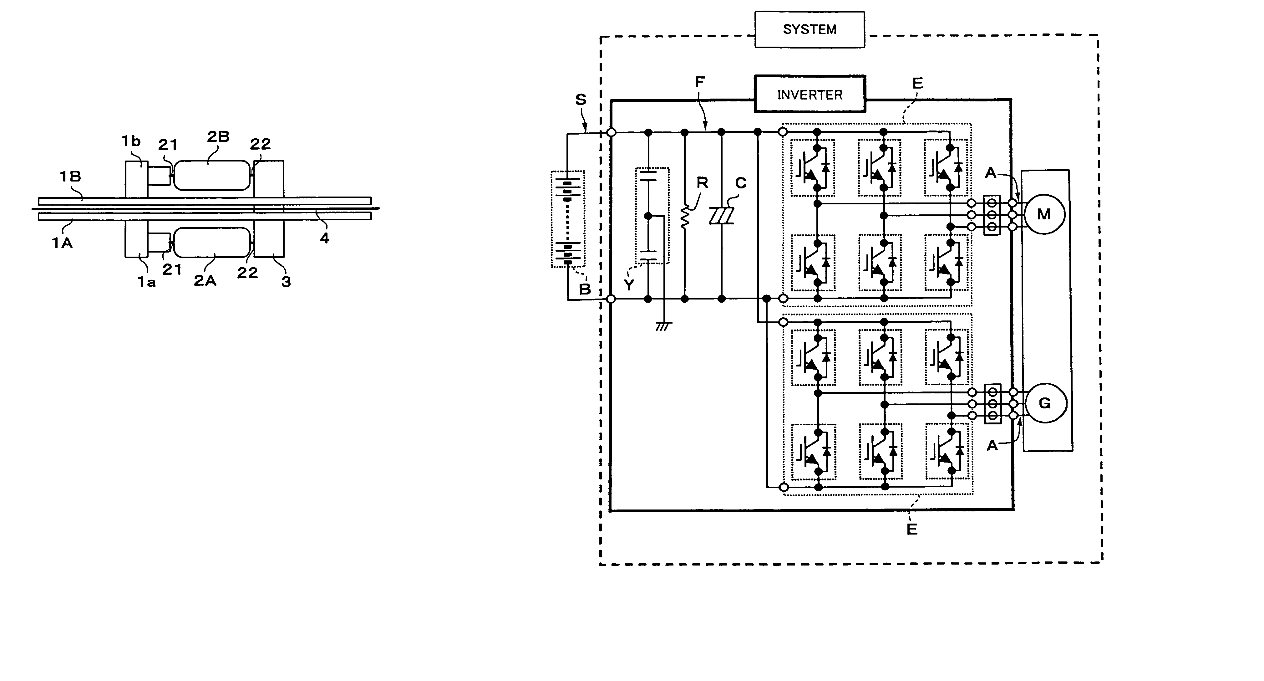
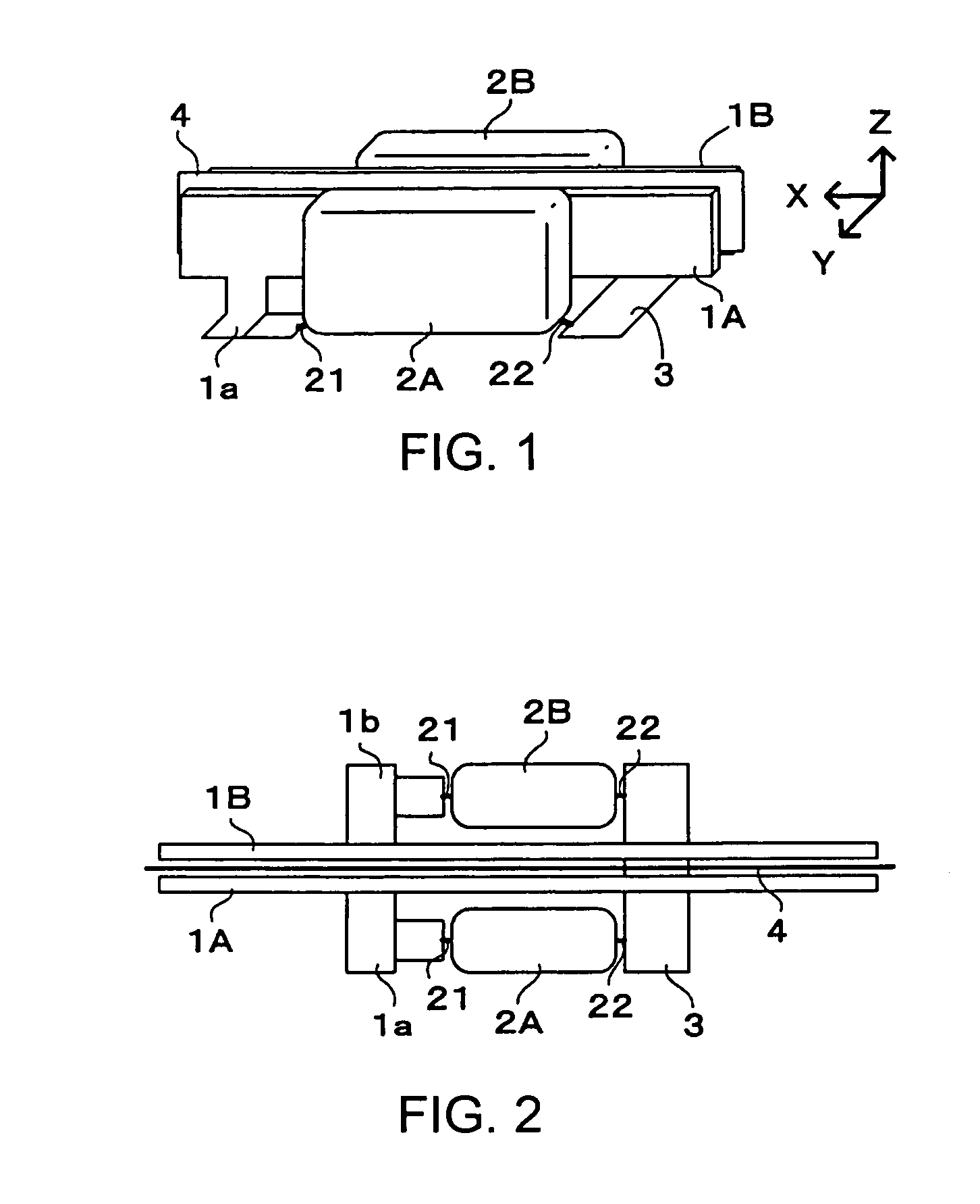
[0021]An embodiment of the invention will now be described with reference to the drawings. FIG. 1 is a perspective view schematically illustrating a device for removing inverter noise. The device is structured so as to ground a pair of bus bars 1A, 1B extending in parallel between a pair of capacitors 2A, 2B. The capacitors 2A, 2B are connected to the bus bars and to a grounding terminal 3 at symmetrical positions holding the pair of bus bars 1A, 1B therebetween. Because of this arrangement, the inductance component is substantially balanced up to a point grounded by the Y-capacitors 2A, 2B on the DC bus line connected to a converter circuit which is a source of noise. Besides, the impedance becomes very small in the front and rear connection lines holding the capacitors 2A, 2B therebetween. Therefore, this structure makes it possible to effectively remove high-frequency noise from the DC circuit of the inverter.

[0022]Here, the bus bars 1A, 1B are strap members with an insulating me...


PUM


Abstract

In a device for removing inverter noise, a pair of bus bars extending in parallel are grounded via a pair of capacitors. The capacitors are connected to the bus bars and to a grounding terminal at positions symmetrical to the pair of bus bars. Therefore, the inductance components are balanced from the source of noise to the grounded point, and impedance components are decreased from the two bus bars to a point grounded through the capacitors, making it possible to effectively remove high-frequency noise on the DC bus line of the inverter without requiring a large amount of space.

Description

[0001]This application claims priority from JP 2003-173952, filed Jun. 18, 2003, the disclosure of which in its entirety is incorporated herein by reference thereto.BACKGROUND OF THE INVENTION[0002]1. Field of Invention[0003]The invention relates to a noise-removing device for removing high-frequency components flowing through a line by grounding a middle point of a DC bus line through a capacitor. More particularly, the invention relates to a noise-removing device adapted to an inverter for controlling electric motors in a drive unit for electric cars and in a drive unit for hybrid cars.[0004]2. Description of Related Art[0005]An inverter for driving electric motors is required by AC electric motors (in this specification, a motor and a generator that also works as a motor are both called electric motors) that are driven by a DC power source, such as a storage battery, as in a drive unit for electric cars and in a drive unit for hybrid cars. In a drive unit mounting, for example, t...

Claims


Application Information

Patent Timeline
IPC IPC(8): H02M1/12H02M1/14B60L9/18H02G3/16H02M7/00H02M7/48
CPCH02M1/12H02M7/003H02M2001/008H02M1/008
Inventor TAGUCHI, SHINKOGA, KIYOTAKAHATTORI, KATSUHIKO
Owner AISIN AW CO LTD
Why Eureka
Try Eureka