Furthermore, if the slope KV is small, the lockup time required before the PLL locks prolongs.
On the other hand, if the slope KV is increased, the stability of the PLL deteriorates.
In addition, increasing the slope KV increases the current consumption and the apparatus area.
Conventionally, therefore, increasing the slope KV is also a problem.
Method used
Image
Click on the blue label to locate the original text in one second.
Reading with bidirectional positioning of images and text.
Examples
first embodiment
(1) FIRST EMBODIMENT
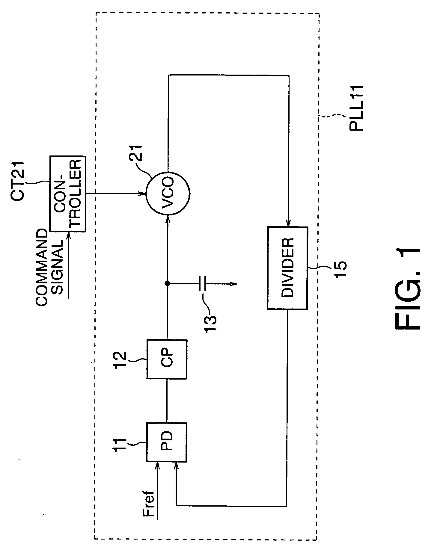
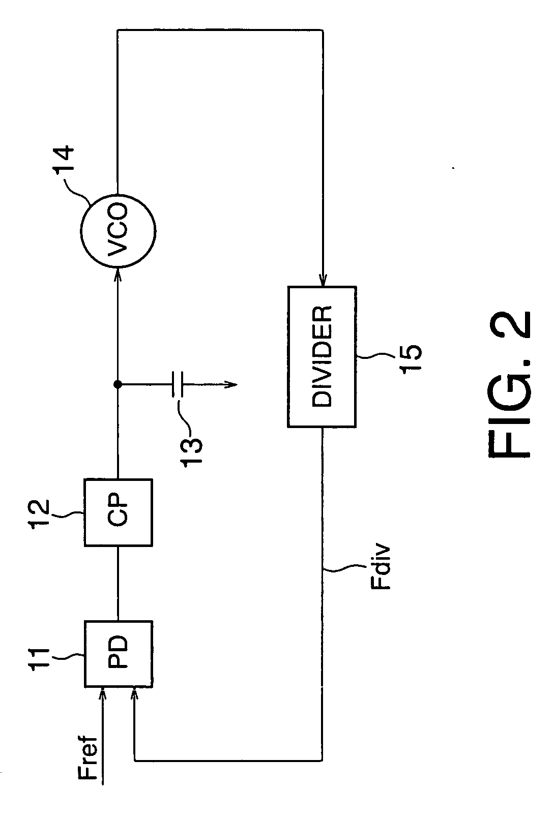
[0063]FIG. 2 shows the arrangement of a PLL as a comparative example.
[0064] A phase detector (to be referred to as a PD hereinafter) 11 compares the phase of a signal having a frequency Fdiv divided by a divider 15 having a frequency dividing ratio N (N>0) with the phase of a signal having a reference frequency Fref supplied by, e.g., a CPU (not shown) which controls the whole system. The phase difference of the frequency Fdiv from the reference frequency Fref is output as the comparison result.
[0065] On the basis of this comparison result, a charge pump (to be referred to as a CP hereinafter) 12 charges or discharges the output terminal, and outputs a control voltage Vctrl based on the comparison result. A loop filter 13 which ensures the stability of the loop is inserted between this output terminal and the ground terminal.
[0066] A VCO 14 is given the control voltage Vctrl output from the CP 12, and outputs an oscillation frequency Fvco based on this voltage...
second embodiment
(2) SECOND EMBODIMENT
[0095] A frequency synthesizer according to the second embodiment of the present invention will be described below with reference to FIG. 12 showing the arrangement of this frequency synthesizer.
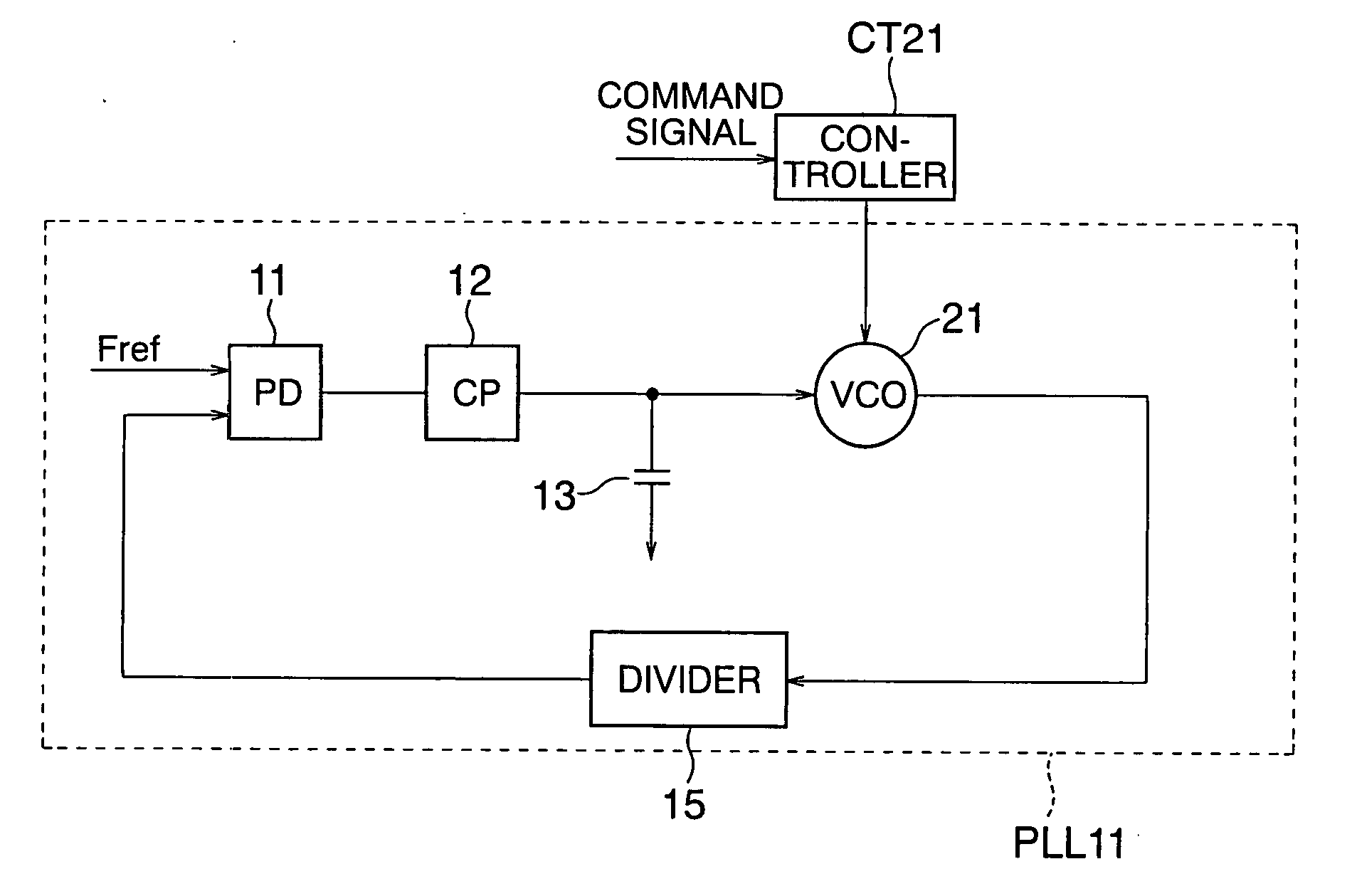
[0096] In the first embodiment shown in FIG. 1, a command signal is supplied to the controller CT21 from a CPU (not shown) or the like. On the basis of this command signal, a control signal is given to the VCO 21, and ON / OFF of each of the switches SW1 to SWn contained in the VCO 21 is controlled. As a consequence, the capacitances C1 to Cn shown in FIG. 6, for example, are selectively added in parallel with the variable capacitance Cv.
[0097] By contrast, in this embodiment, a comparator COM41 compares a control voltage Vctrl, which is output from a CP 12 to a VCO 21, with a reference voltage Vref1, and supplies the comparison result to a controller CT41. On the basis of this comparison result, the controller CT41 supplies a control signal to the VCO 21. In the VCO 21,...
third embodiment
(3) THIRD EMBODIMENT
[0122] A frequency synthesizer according to the third embodiment of the present invention will be described below with reference to FIG. 17 showing the arrangement of this frequency synthesizer.
[0123] This embodiment includes a PD 11, a CP 12, a loop filter 13, a VCO 21, a divider 15, a PLL 31 having a voltage switch SW100 which connects the output terminal of the CP 12 or a reference voltage Vref2 to the input terminal of the loop filter 13, a counter CTR51, a comparator COM51, and a controller CT51.
[0124] Before the voltage switch SW100 connects the output terminal of the CP (Charge Pump) 12 to the input terminal of the loop filter 13 and the PLL 31 starts a normal operation, the output terminal of the CP 12 and the input terminal of the loop filter 13 are separated to form an open loop. The reference voltage Vref2 is input to the input terminal of the loop filter 13, and a control voltage Vctrl is applied to the VCO 21 via the loop filter 13. Reference symbo...
PUM
Abstract
According to the present invention, there is provided a frequency synthesizer comprising: a phase locked loop circuit which receives a reference signal having a reference frequency and a first signal having a first frequency, compares phases of the reference signal and first signal, applies a control voltage based on a phase comparison result to an input terminal of a voltage controlled oscillator to generate a second signal having an oscillation frequency and output the second signal from an output terminal, and supplies the second signal to a divider to divide the frequency of the second signal and output the first signal; and a controller which generates and supplies a control signal to the voltage controlled oscillator, wherein the voltage controlled oscillator has an arrangement in which a coil and variable capacitance are connected in parallel between the input terminal and output terminal, and one of a plurality of capacitances is selectively connected between the input terminal and output terminal by a switch in parallel with the variable capacitance, and ON / OFF of the switch is controlled by the control signal.
Description
CROSS REFERENCE TO RELATED APPLICATION [0001] This application is based upon and claims benefit of priority under 35 USC §119 from the Japanese Patent Application No. 2004-371097, filed on Dec. 22, 2004, the entire contents of which are incorporated herein by reference. BACKGROUND OF THE INVENTION [0002] The present invention relates to a frequency synthesizer and, more particularly, to a frequency synthesizer having a phase locked loop (to be referred to as a PLL hereinafter). [0003] The PLL is used to allow a voltage controlled oscillator (to be referred to as a VCO hereinafter) to oscillate at a predetermined frequency. [0004] The PLL cannot oscillate over a wide frequency range if a slope KV of an F-V curve which indicates the relationship between a frequency F and control voltage Vctrl is small, i.e., if the gain is small. [0005] Also, the F-V curve generally varies in accordance with, e.g., the temperature or manufacturing conditions. Therefore, the PLL cannot oscillate at a d...
Claims
Application Information
Patent Timeline
Application Date:The date an application was filed.
Publication Date:The date a patent or application was officially published.
First Publication Date:The earliest publication date of a patent with the same application number.
Issue Date:Publication date of the patent grant document.
PCT Entry Date:The Entry date of PCT National Phase.
Estimated Expiry Date:The statutory expiry date of a patent right according to the Patent Law, and it is the longest term of protection that the patent right can achieve without the termination of the patent right due to other reasons(Term extension factor has been taken into account ).
Invalid Date:Actual expiry date is based on effective date or publication date of legal transaction data of invalid patent.

