Snare drum stand lock adjustment

a technology for adjusting the lock and snare drum, which is applied in the direction of strings, instruments, musical instruments, etc., can solve the problems of loosened up, easy damage to the lever, and failure to secure the lock, and achieve the effect of easy and stable locking of the stand

a technology for adjusting the lock and snare drum, which is applied in the direction of strings, instruments, musical instruments, etc., can solve the problems of loosened up, easy damage to the lever, and failure to secure the lock, and achieve the effect of easy and stable locking of the stand

US7087827B2Active Publication Date: 2006-08-08LIAO CHI CHING

Image

  • Snare drum stand lock adjustment
  • Snare drum stand lock adjustment
  • Snare drum stand lock adjustment

Examples


Embodiment Construction

[0015]The following descriptions are of exemplary embodiments only, and are not intended to limit the scope, applicability or configuration of the invention in any way. Rather, the following description provides a convenient illustration for implementing exemplary embodiments of the invention. Various changes to the described embodiments may be made in the function and arrangement of the elements described without departing from the scope of the invention as set forth in the appended claims.

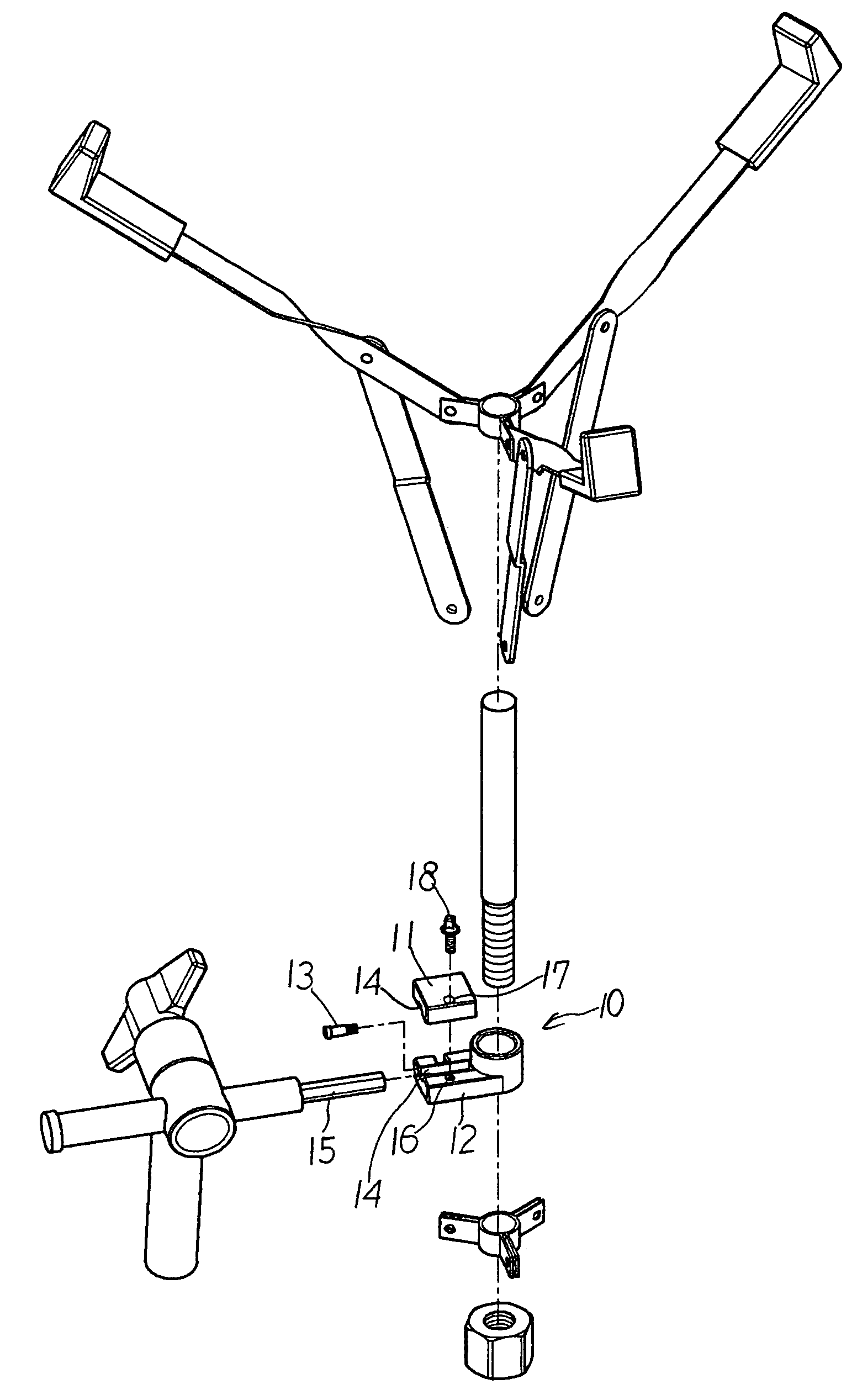
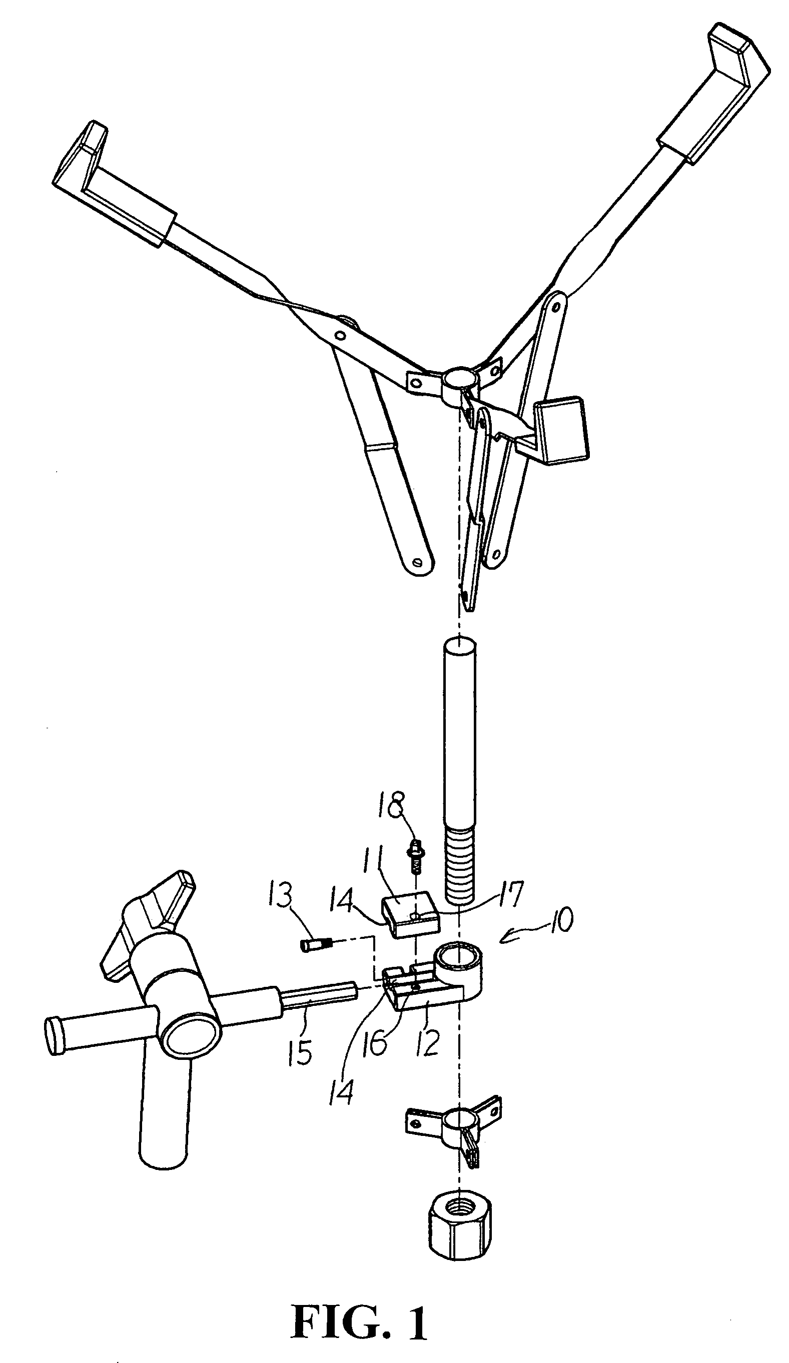
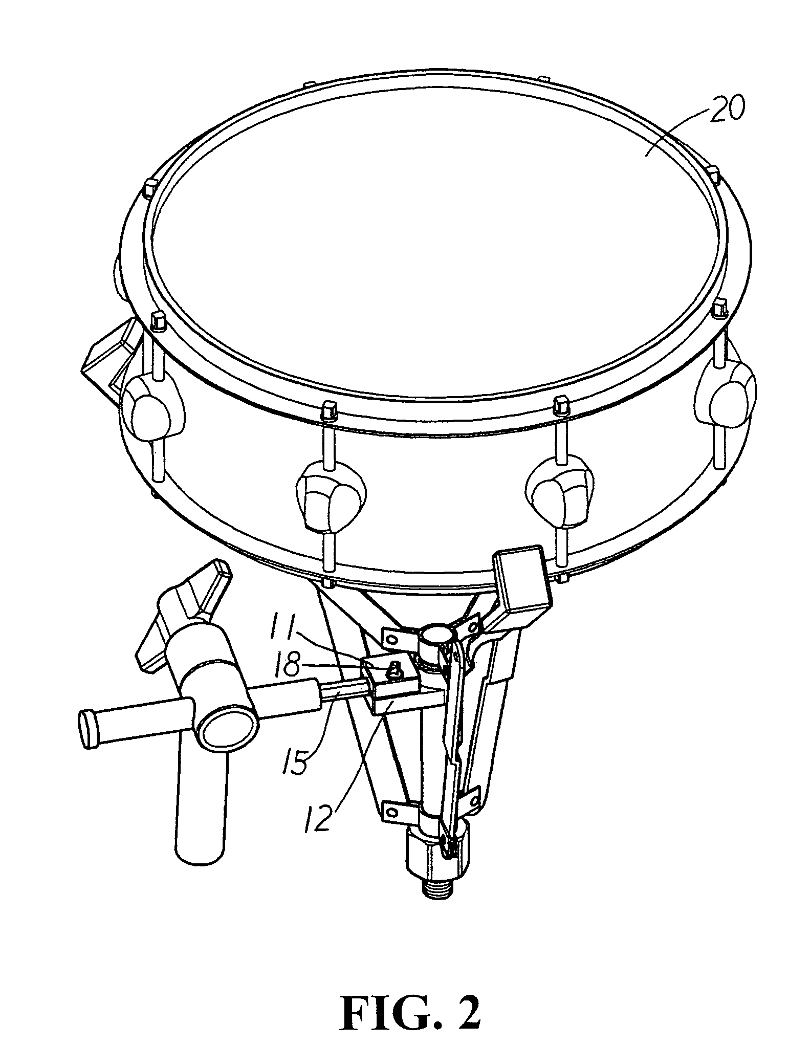
[0016]Referring to FIGS. 1, 2, and 3, a lock adjustment (10) of a snare drum stand is comprised of two plates including an upper plate (11) and a lower plate (12). On one side of the lowerplate (12), a slot is provided and a corresponding ear is provided on the upper plate (11) to receive insertion of an axial pin (13) for the lock adjustment to pivot on a connector. Each plate (11, 12) is recessed at its center for both plates (11, 12) when pivoted to define a channel (14) in a form approximatel...


PUM


Abstract

A snare drum stand lock adjustment comprised of two plates containing an inner channel to merely clamp a lever of a connector; both plates being pivoted to each other on one side with an axial pin; one end of the lock adjustment being fastened to a brace of the stand and the other end receiving insertion of a lever from a connector to permit easy and secure operation of the lock adjustment.

Description

BACKGROUND OF THE INVENTION[0001](a) Technical Field of the Invention[0002]The present invention is related to a lock adjustment of a snare drum stand, and more particularly, to one has the lever from a connector clamped by two plates pivoted to each other then fastened on the end to the brace of the stand.[0003](b) Description of the Prior Art[0004]Musical instruments are usually assembled with multiple accessories interlocked to one another. Bolts or nuts and locking plates are used for the assembly purpose. As illustrated in FIGS. 4, 5, and 6 of the accompanying drawings, a snare drum stand has a tube (30) as the primary support adapted with a lever (31) locked to a brace (32) at the top of the stand. Wherein, the level (31) is related to a polygonal provided in a given direction and a lock adjustment (33) is provided to connect the lever (31) and the stand. One end of the lock adjustment (33) is inserted with a shaft (34) that holds the brace (32) while the other end extending o...

Claims


Application Information

Patent Timeline
08 Aug 2006
Publication
US7087827B2
IPC
G10D13/02
CPC
G10D13/026; G10D13/02; G10D13/28
Inventors
LIAO, CHI-CHING