
Seating unit with adjustable lumbar device

Active Publication Date: 2006-08-29
STEELCASE INC
View PDF67 Cites 112 Cited by
  • Summary
  • Abstract
  • Description
  • Claims
  • Application Information

AI Technical Summary

Benefits of technology

[0006]In one aspect of the present invention, a seating unit includes a back support, a back cover located on a front surface of the back support but separated from the back support in a lumbar area of the back cover, and a lumbar device adjustably positioned between the back support and the back cover. The lumbar device is selectively moveable to change a shape of the back cover in the lumbar area. The lumbar device includes a unitary sheet with first panel-like wall portions formed to define a first surface and second panel-like wall portions formed to define a second surface. Third wall portions extend between the first and second wall portions to define space therebetween. The first and second wall portions are configured to slidingly engage the front surface of the back support and a rear surface of the back cover, respectively. By this arrangement, vertical movement of the lumbar device causes a shape change of the back cover for providing improved lumbar support to a seated user.
[0009]In another aspect of the present invention, a seating unit includes a back support, a back cover located on a front surface of the back support but separable therefrom at least in a lumbar area of the back cover, and a lumbar device adjustably positioned between the back support and the back cover. The lumbar device includes a flexible sheet configured to slidingly engage the front surface of the back support and a rear surface of the back cover, respectively. The lumbar device further includes a wire that extends across and supports the flexible sheet, and still further includes handles that track along edges of the back support and yet still further includes stretchable material that connects the handles to respective ends of the wire. Thus, vertical movement of the lumbar device causes a shape change of the back cover for providing improved lumbar support to a seated user.

Problems solved by technology

However, the wires tend to flex in a manner that reduces the ability of a lumbar panel to slide smoothly up and over each wire during vertical adjustment.

Method used


Image

  • Seating unit with adjustable lumbar device
  • Seating unit with adjustable lumbar device
  • Seating unit with adjustable lumbar device

Examples


Embodiment Construction

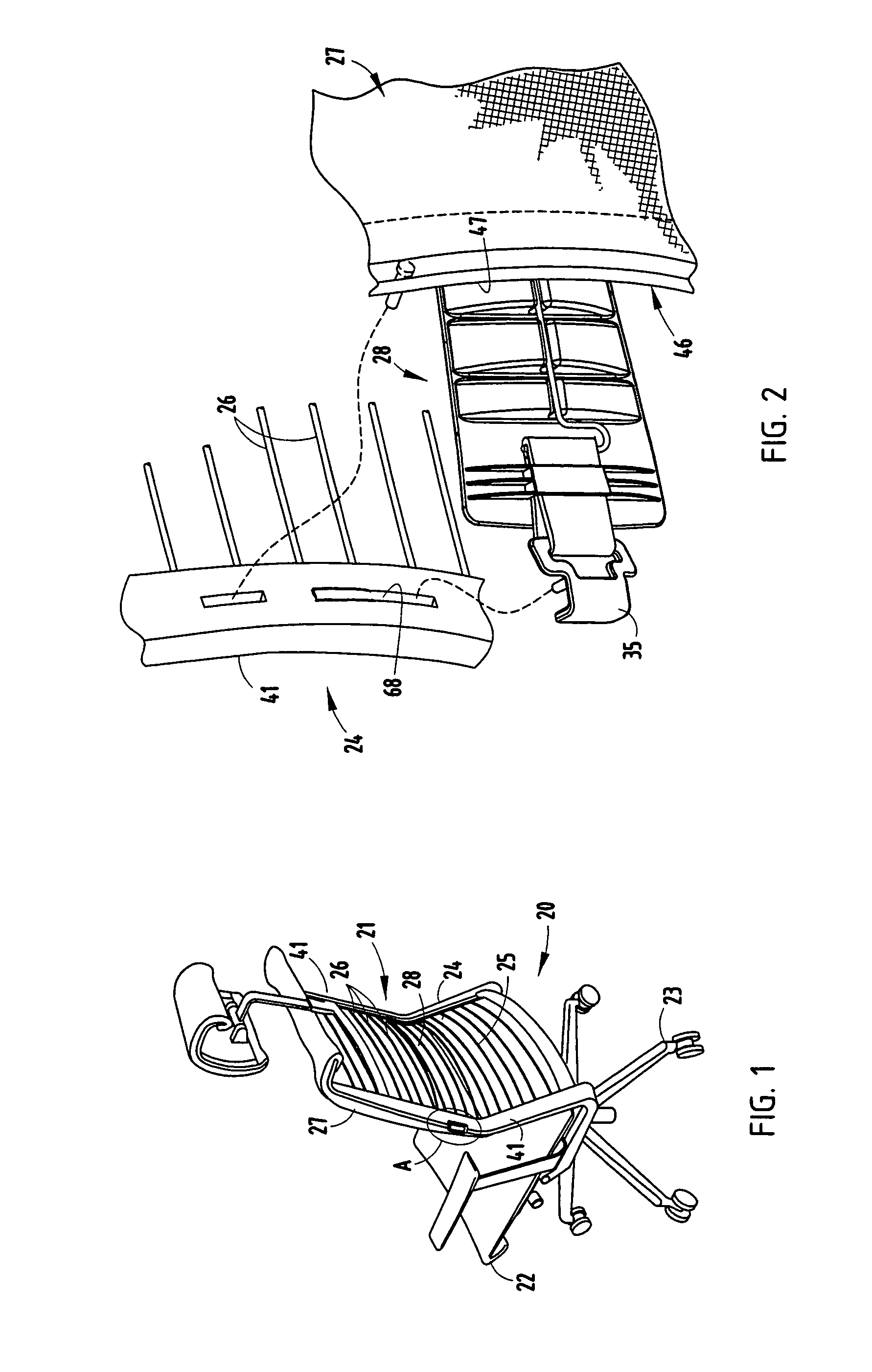
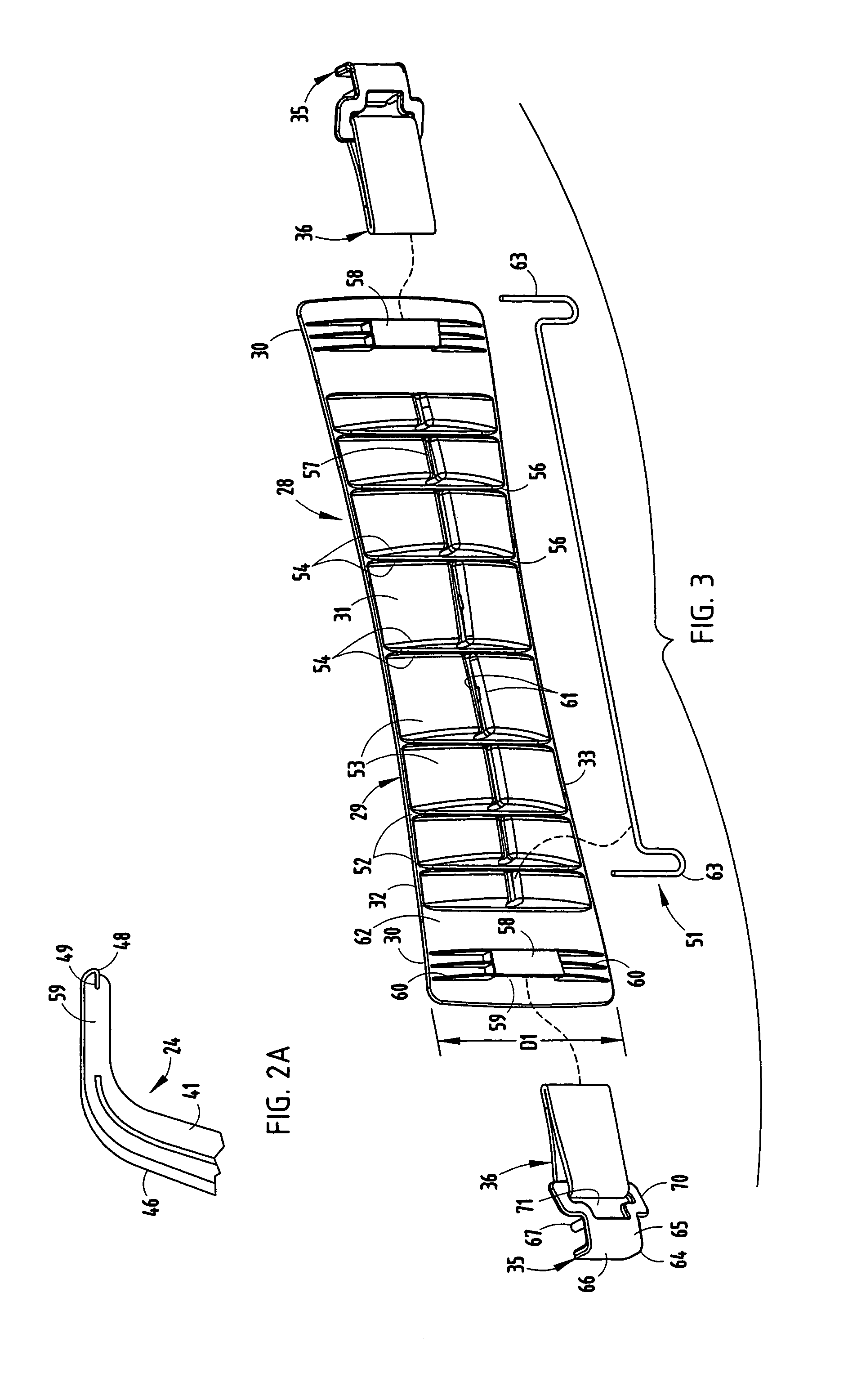
[0022]A seating unit 20 (FIG. 1) includes a back support 21 and seat 22 supported for synchronous movement by a base 23. The back support 21 includes a perimeter frame 24 defining an opening 25, and includes a plurality of resilient members 26 (i.e. steel wires) spanning the opening and operably supported for flexing for supporting a seated user. An upholstery cover 27 extends over and covers the resilient members 26 and covers a front of the perimeter frame 24. A bow-tie-shaped lumbar device 28 is positioned between the cover 27 and sides of the perimeter frame 24 for vertical adjustment. The lumbar device 28 includes a bow-tie-shaped flexible body 29 with end sections 30 defining a greater vertical dimension D1 than a middle section 31 of the body 29. Upper and lower edges 32 and 33 of the end sections 30 are thin and serve to wedgingly slip between the cover 27 and the resilient members 26 in a manner leading the middle over irregular surfaces between the resilient members 26. A ...


PUM


Abstract

A seating unit includes a back support with a perimeter frame defining an opening, and a plurality of resilient members spanning the opening. An upholstery cover extends over and covers the resilient members and a front of the perimeter frame. A bow-tie-shaped lumbar device is positioned between the cover and sides of the perimeter frame for vertical adjustment. The lumbar device includes a body with end sections defining a greater dimension than a middle of the body. Upper and lower edges of the end sections are thin and serve to wedgingly slip between the cover and the resilient members in a manner leading the middle over irregular surfaces between the resilient members. A thick area between the upper and lower edges causes a change in lumbar support force and shape as the lumbar device is adjusted. Handles are attached to the body by stretchable fabric.

Description

CROSS REFERENCE TO RELATED APPLICATIONS[0001]This application is a continuation-in-part of co-assigned co-invented application Ser. No. 10 / 792,309, filed Mar. 3, 2004, entitled COMBINED TENSION AND BACK STOP FUNCTION FOR SEATING UNIT now U.S. Pat. No. 6,932,430, which is a continuation-in-part of Ser. No. 10 / 455,076, filed Jun. 5, 2003, entitled COMBINED TENSION AND BACK STOP FUNCTION FOR SEATING UNIT now U.S. Pat. No. 6,880,886, the entire contents of which are incorporated herein in their entirety.BACKGROUND[0002]The present invention relates to adjustable lumbar devices for seating units.[0003]Modern chairs and seating units are often provided with adjustable lumbar devices to allow the chair's back to be adjusted for different amounts of lumbar support, as required and desired by different users. However, new lumbar devices are desired that are simpler to manufacture and assemble, and that include less components, lower cost components, and components that function more effectiv...

Claims


Application Information

Patent Timeline
IPC IPC(8): A47C3/025A47C3/026A47C1/032A47C7/38
CPCA47C1/03255A47C7/46A47C7/38
Inventor BATTEY, ROBERT JJOHNSON, ERICHADLEY, JONATHAN B.PETERSON, GORDON J.
Owner STEELCASE INC
Learn More