Encasement for handheld computer

a handheld computer and encasement technology, applied in the field of handheld computers, can solve the problems of increased footprint, disadvantageous pivot arrangement (or book open style), and relatively complex multiple linkage structure of 360° hinge arrangemen

Inactive Publication Date: 2006-08-29
QUALCOMM INC
View PDF62 Cites 84 Cited by
  • Summary
  • Abstract
  • Description
  • Claims
  • Application Information

AI Technical Summary

Benefits of technology

[0012]According to another aspect of an embodiment of the present invention, a handheld computer comprises a housing and a cover movably connected thereto by a unitary hinge assembly. The unitary hinge assembly enables the cover to be moved to at least two different positions. The cover provides a different function in each position.

Problems solved by technology

The 180° pivot arrangement (or book open style) can be disadvantageous when desk space is limited or the computer is being held in the user's hand because the “footprint” of the handheld computer is doubled in this configuration.
The 360° pivot arrangement does not have the disadvantage of an increased footprint, however, the heretofore known 360° hinge arrangements are relatively complex multiple linkage structures.
At this angle, it can be difficult to operate the computer and view the display screen.
However, the use of a separate cradle is disadvantageous because, like the separate cases, the cradle must be separately accounted for and stored when not in use.
In addition, the heretofore known cradles are relatively bulky structures and thus they are cumbersome to transport and store when not in use.
Although some recently designed handheld computers have encasements with hinged covers that can be reconfigured to function as a stand or base to position the computer housing at a desirable working angle, the hinges of these arrangements are relatively complex multi-part structures.
Moreover, the hinges typically allow rotation of the cover in very limited ways.

Method used


Image

  • Encasement for handheld computer
  • Encasement for handheld computer
  • Encasement for handheld computer

Examples


second embodiment

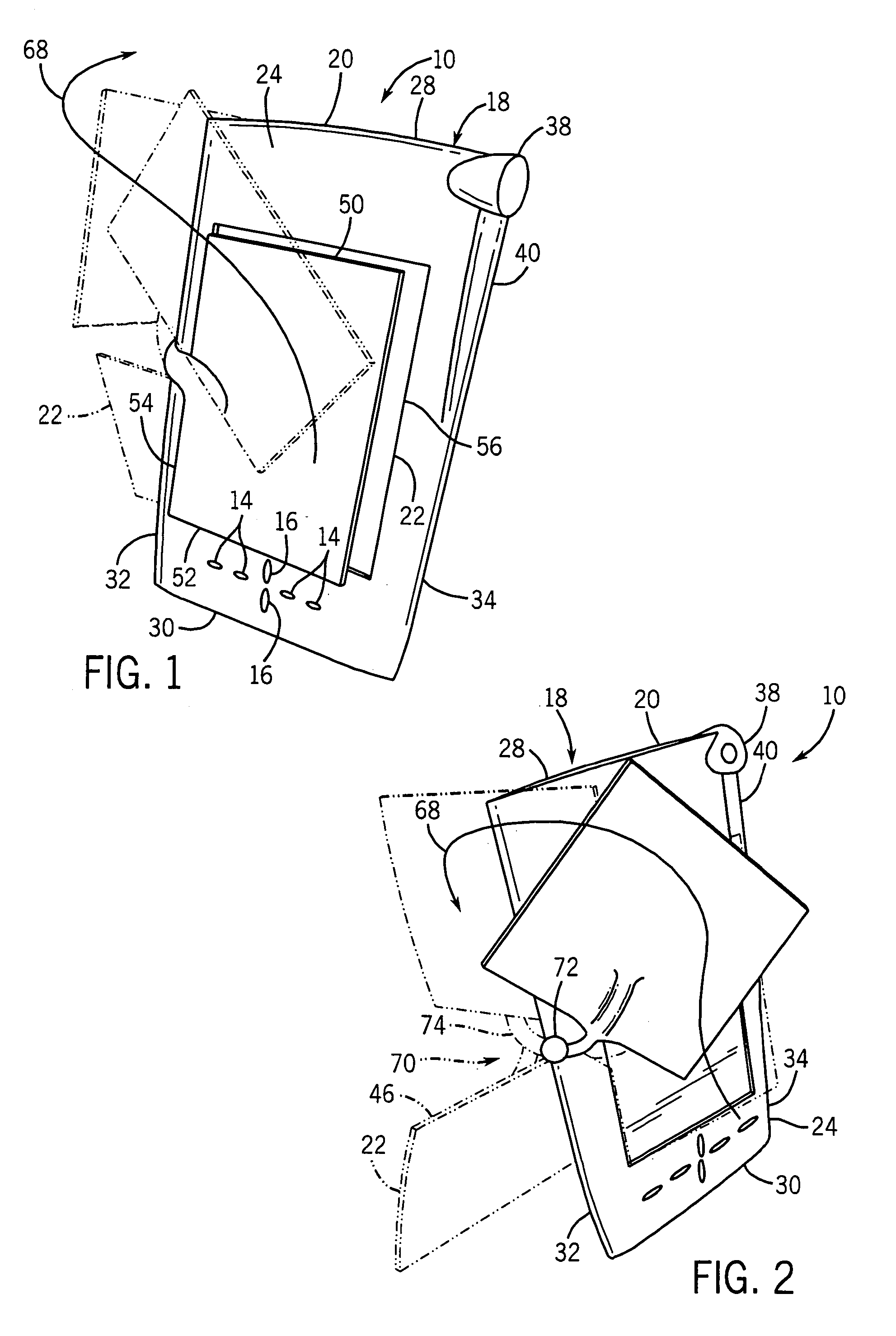
[0057]Referring now to FIGS. 5–8, a handheld computer 110 is shown. For brevity, the description of handheld computer 110 will be generally limited to its differences relative to handheld computer 10 described above. For convenience, elements of handheld computer 110 that are substantially similar to corresponding elements of handheld computer 10 will be identified by the same reference numerals but preceded by a “1”.

[0058]Handheld computer 110 differs from handheld computer 10 described above in that proximal end 162 of arm 160 is pivotally coupled to left edge 132 of housing 120 at a location that is substantially below horizontal midline 176 of display 112 and housing 120. In addition, distal end 164 of arm 160 is fixedly coupled to left edge 154 of cover 122 at a lower location than described above for the attachment of arm 60 to cover 22. As a result, bottom edge 152 of cover 122 in the stand position does not lie substantially along vertical midline 178 of rear face 126 of hou...

third embodiment

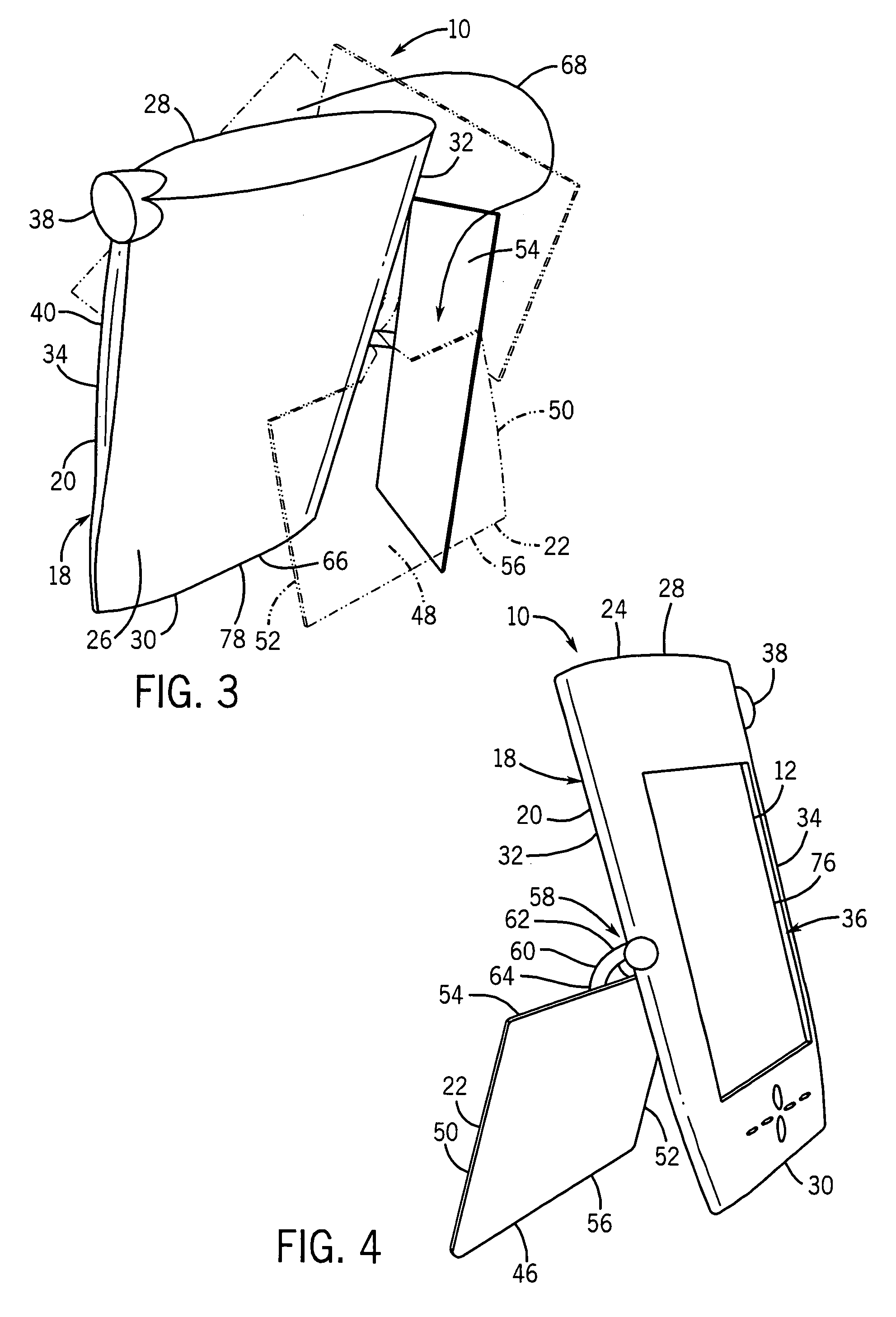
[0059]Referring now to FIGS. 9–13, a handheld computer 210 is shown. For brevity, the description of handheld computer 210 will be generally limited to its differences relative to handheld computer 110 described above. For convenience, elements of handheld computer 210 that are substantially similar to corresponding elements of handheld computer 110 will be identified by the same reference numerals but preceded by a “2” instead of a “1”.

[0060]Handheld computer 210 differs from handheld computer 110 described above in that cover 222 when in the stand position is in a “portrait” orientation rather than a “landscape” as with cover 122. In particular, cover 222 in the stand position has top edge 250 resting on horizontal support surface 266 and corner 280 engaged with a well or recess 282 formed in rear face 226 of housing 220. With this arrangement, right edge 256 of cover 222 when in the stand position extends beyond vertical midline 278 of rear face 226 of housing 220. In a preferred...

fourth embodiment

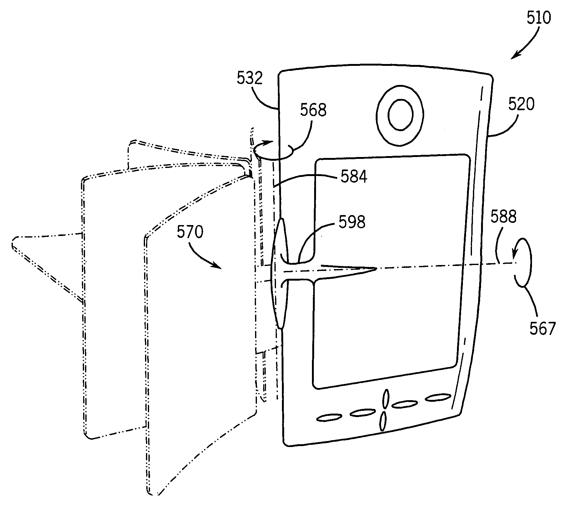
[0061]Referring now to FIGS. 14–18, a handheld computer 310 is shown. For brevity, the description of handheld computer 310 will be generally limited to its differences relative to handheld computer 10 described above. For convenience, elements of handheld computer 310 that are substantially similar to corresponding elements of handheld computer 10 will be identified by the same reference numerals but preceded by a “3”.

[0062]Handheld computer 310 differs from handheld computer 10 described above in that proximal end 362 of arm 360 is pivotally coupled to the midpoint of bottom edge 330 of housing 320 rather than to the midpoint of left side edge 332 (as with handheld computer 10). As a result, cover 322 in the stand position has its inner surface 346 (rather than one of its edges) in contact with horizontal support surface 366.

[0063]In FIG. 18, arrow 368 shows cover 322 being moved from the closed position to the stand position by flipping cover 322 about an axis 384 extending along...


PUM


Abstract

A handheld computer comprises a generally rectangular housing and a cover movably connected thereto by a hinge assembly. The hinge assembly includes a tubular member or arm that has one end fixedly (non-rotatably) secured to an edge of the cover and an opposite end pivotally coupled to an edge of the cover. The hinge assembly enables the cover to be moved to at least three different positions. The cover provides a different function in each position. The hinge assembly comprises a pin and slot arrangement.

Description

CROSS-REFERENCE TO RELATED PATENT APPLICATIONS[0001]This application is a divisional application of U.S. application Ser. No. 10 / 158,335, filed on May 30, 2002, now U.S. Pat. No. 6,781,824, which claims the benefit of Provisional application Ser. No. 60 / 352,785, filed Jan. 29, 2002 the entirety of which is incorporated herein by reference.FIELD OF THE INVENTION[0002]The present invention relates to the field of handheld computers and, more particularly, to handheld computers having encasements that can be reconfigured to perform multiple functions. The present invention also relates to a method of repositioning an encasement of a handheld computer to provide multiple functions.BACKGROUND OF THE INVENTION[0003]Handheld computers, including personal digital assistants (“PDAs”) and palm-sized computers, traditionally provide the user with a wide variety of functions, such as a calendar, an address book, a task list, a notepad, and a calculator. More advanced handheld computers also pro...

Claims


Application Information

Patent Timeline
Patent Type & Authority Patents(United States)
IPC IPC(8): G06F1/16H04L12/28H04L12/56H04M1/02H04M1/72412H04M3/56H04M7/00H04N7/14
CPCG06F1/1626H04M1/0283H04N7/142H04N7/147H04N21/41407H04N21/4438H04N21/4788H04N21/6125H04N21/6175G06F1/166Y10T16/524G06F2200/1634H04M1/0208H04M1/7253H04M2250/02H04W88/02H04M1/72412
Inventor KRIEGER, JOHN WILLIAMLEWIS, RANDALL CLARK
Owner QUALCOMM INC
Why Eureka
Try Eureka