Sliding member

a technology of sliding member and sliding shaft, which is applied in the direction of shaft and bearing, mechanical equipment, rotary machine parts, etc., can solve the problems of material strength decline and material strength decrease, and achieve the effects of improving anti-seizure properties, reducing friction coefficient, and improving lubricity

Inactive Publication Date: 2006-09-05
DAIDO METAL CO LTD
View PDF9 Cites 10 Cited by
  • Summary
  • Abstract
  • Description
  • Claims
  • Application Information

AI Technical Summary

Benefits of technology

[0017]Since the oil contributes to the improvement of lubricity, coefficient of friction can be reduced and anti-seizure property can be improved by adding the oil to the sliding layer. In this case, if the content of the oil is less than 0.1 vol %, the effect to improve lubricity by the oil cannot be obtained, and if it exceeds 15 vol %, wear resistance is deteriorated. Therefore, the content of the oil is preferably 0.1–15 vol %. Examples of the oil are mineral oil, synthetic oil, etc.

Problems solved by technology

Furthermore, since decrease of material strength in a high-temperature atmosphere and decrease of material strength caused by heat generated during the sliding operation are small, satisfactory wear resistance can be maintained even during the sliding at high temperatures.

Method used


Image

  • Sliding member
  • Sliding member

Examples


Embodiment Construction

[0020]The embodiments of the present invention will be explained below.

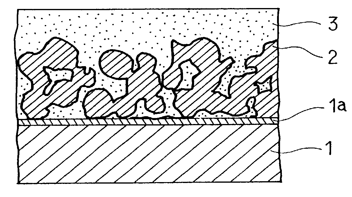
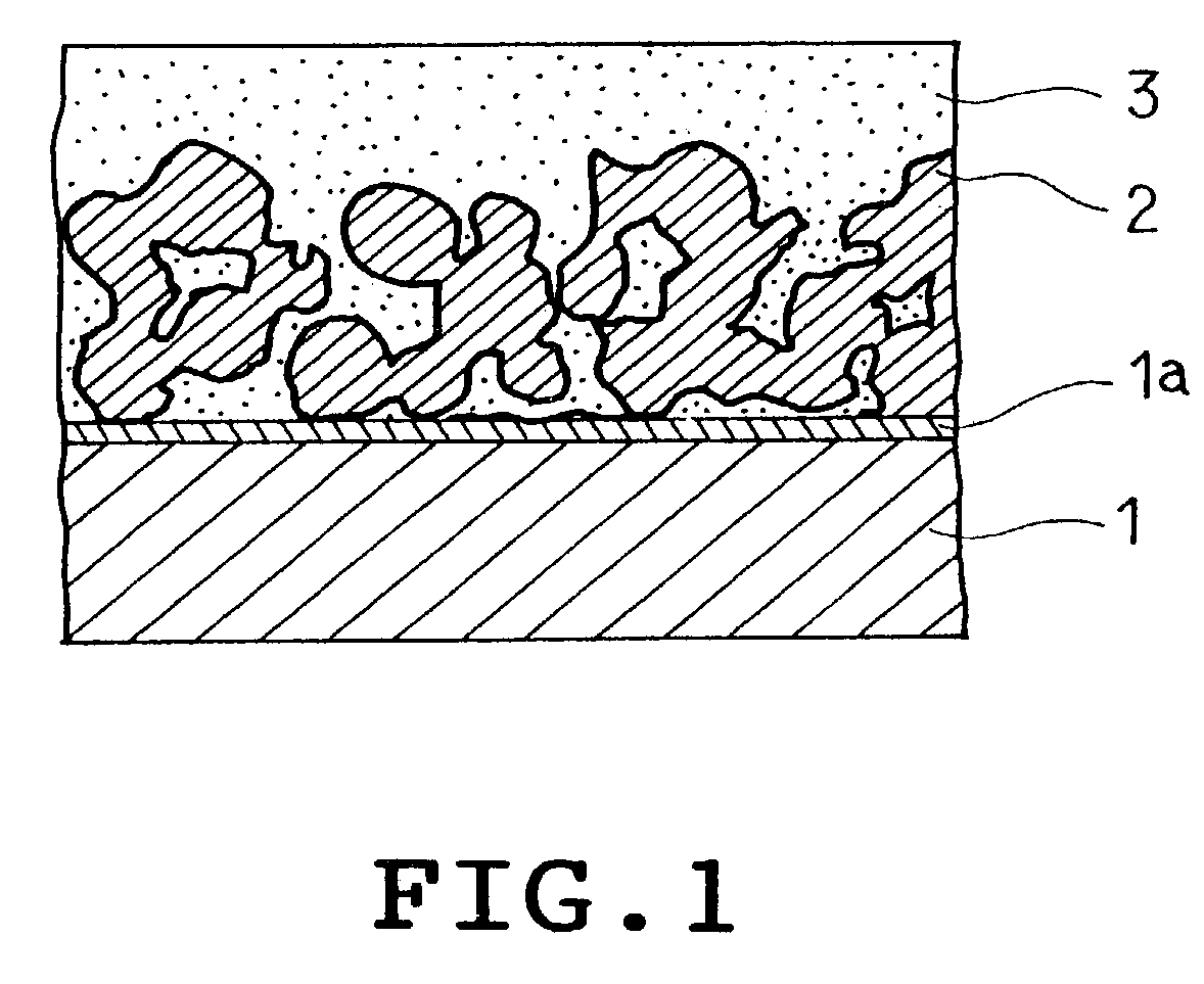
[0021]FIG. 1 is a sectional view of a sliding member which schematically illustrates an embodiment of the present invention. The sliding member is produced in the following manner. A plating layer 1a comprising copper or the like is provided on the surface of a substrate 1 comprising stainless steel or carbon steel, and a porous layer 2 is provided by spreading metal powders of a copper alloy or the like on the surface of the plating layer 1a and sintering the metal powders. Then, the porous layer 2 is impregnated with a sliding layer composition (namely, a mixture of PBI which is a base resin, a solid lubricant such as molybdenum disulfide and, if necessary, hard particles and oil) diluted with a suitable organic solvent, thereby allowing the composition to enter into the pores and coating the porous layer 2 with the composition, followed by heating to cure the composition. Thus, the sliding layer composition co...


PUM

PropertyMeasurementUnit
thicknessaaaaaaaaaa
thicknessaaaaaaaaaa
diameteraaaaaaaaaa

Abstract

A sliding member includes a substrate, a porous layer provided on the surface of the substrate and a sliding layer with which the porous layer is impregnated and coated. The sliding layer contains polybenzimidazole, 1–70 vol % of a solid lubricant and 0.1–10 vol % of hard particles.

Description

CROSS-REFERENCE TO RELATED APPLICATIONS[0001]This application claims priority based on Japanese Application No. 2002-174279, filed Jun. 14, 2002.BACKGROUND OF THE INVENTION[0002]The present invention relates to a sliding member having a sliding layer on a sliding surface.[0003]Sliding members, for example, plain bearings for engines of automobiles are usually improved in wear resistance, anti-seizure property and initial conformability by providing a sliding layer comprising a thermosetting resin such as a polyamide-imide (hereinafter referred to as “PAI”) resin, a polyimide (hereinafter referred to as “PI”) resin or an epoxy (hereinafter referred to as “EP”) resin containing a solid lubricant or the like on the surface of a substrate comprising a back metal made of a steel plate and a bearing alloy layer provided on the back metal (see, for example, JP-A-4-83914 and JP-A-9-79262).[0004]Furthermore, JP-A-8-59991 discloses resin-based sliding materials comprising PAI and PI as base r...

Claims


Application Information

Patent Timeline
Patent Type & Authority Patents(United States)
IPC IPC(8): F16C33/20F16C33/10F16C33/12
CPCF16C33/10F16C33/201F16C33/12Y10S384/902F16C33/206F16C2202/54F16C2208/02F16C2208/44
Inventor HIRAMATSU, NOBUTAKATANAKA, TAKUYANAKAJIMA, HIDEYUKIFUJITA, MASAHITOSHIBAYAMA, TAKAYUKI
Owner DAIDO METAL CO LTD
Why Eureka
Try Eureka