
Belt clip device for mobile communication terminal unit

a mobile communication terminal and clip device technology, applied in the direction of transmission, garments, applications, etc., can solve the problem of difficulty for users to accurately confirm the displayed information or conten

Inactive Publication Date: 2006-09-19
LG INFORMATION & COMM LTD
View PDF13 Cites 33 Cited by
  • Summary
  • Abstract
  • Description
  • Claims
  • Application Information

AI Technical Summary

Benefits of technology

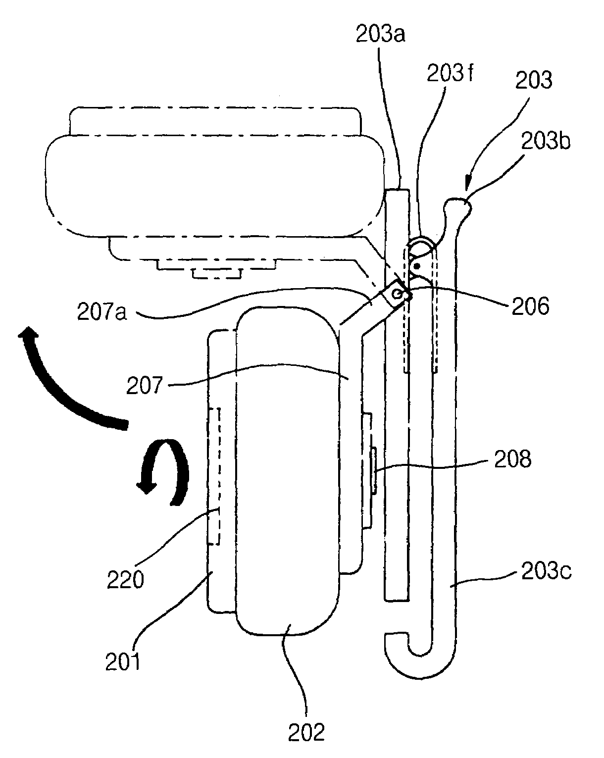
[0010]Therefore, the present invention has been made in view of the above mentioned problems, and an object of the invention is to provide a belt clip device for a mobile communication terminal unit which includes a terminal unit holder and a clamp hingably connected together, thereby allowing the user to rapidly and accurately view the display window of the terminal unit in a state carrying the terminal unit at his side.
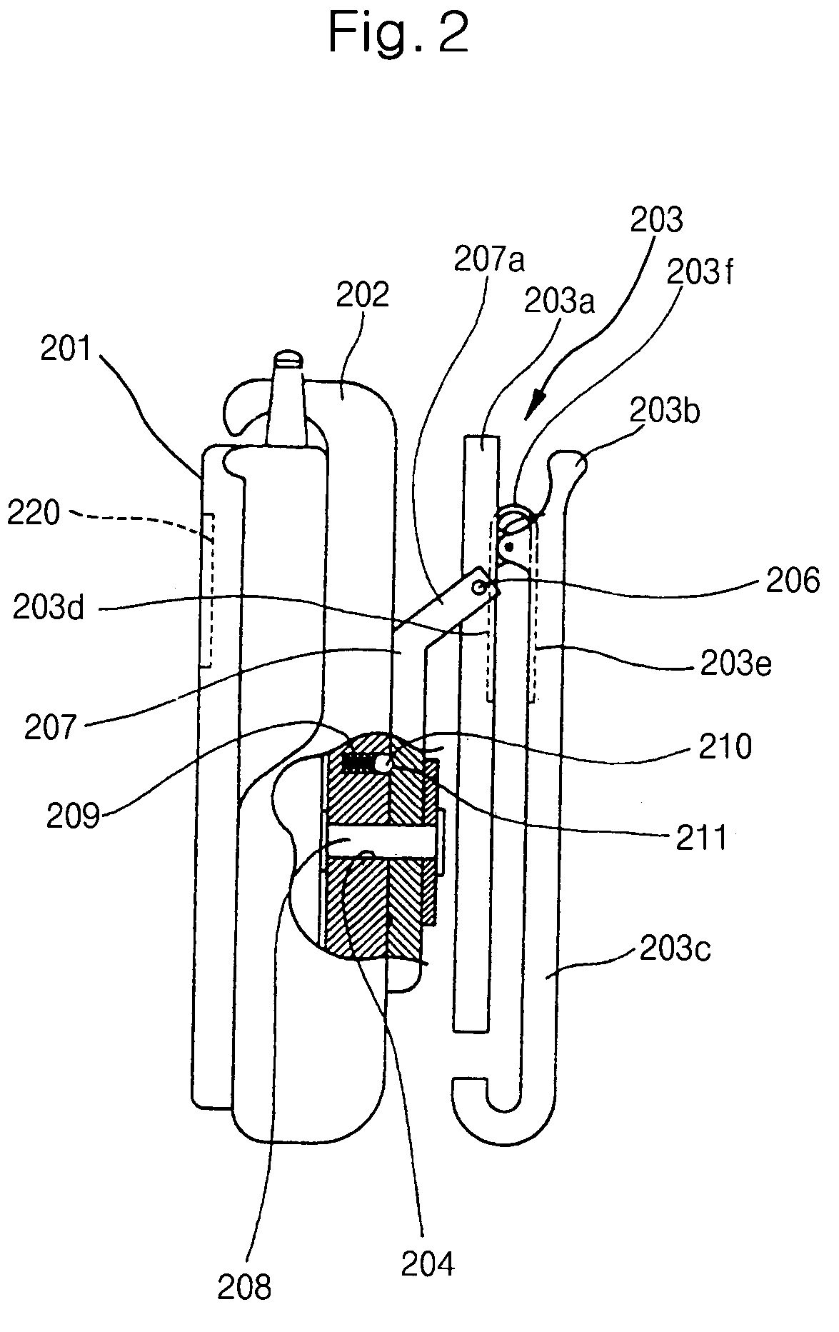
[0018]Preferably, each of the rotating shaft supporting members has a recessed structure for receiving and holding one end of an associated one of the rotating shafts, the rotating shaft end being protruded from the rotating shaft holding member. In this case, each of the rotating shafts is provided at the one end thereof with an engagement protrusion adapted to engage with a selected one of the engagement grooves formed at an associated one of the rotating shaft supporting members, thereby causing the terminal unit holder to be held at a position defined by the engagement groove engaged with the engagement protrusion with respect to the clamp.

Problems solved by technology

As a result, it is difficult for the user to accurately confirm the displayed information or content.

Method used


Image

  • Belt clip device for mobile communication terminal unit
  • Belt clip device for mobile communication terminal unit
  • Belt clip device for mobile communication terminal unit

Examples


Embodiment Construction

[0029]Now, preferred embodiments of the present invention will be described in conjunction with the annexed drawings.

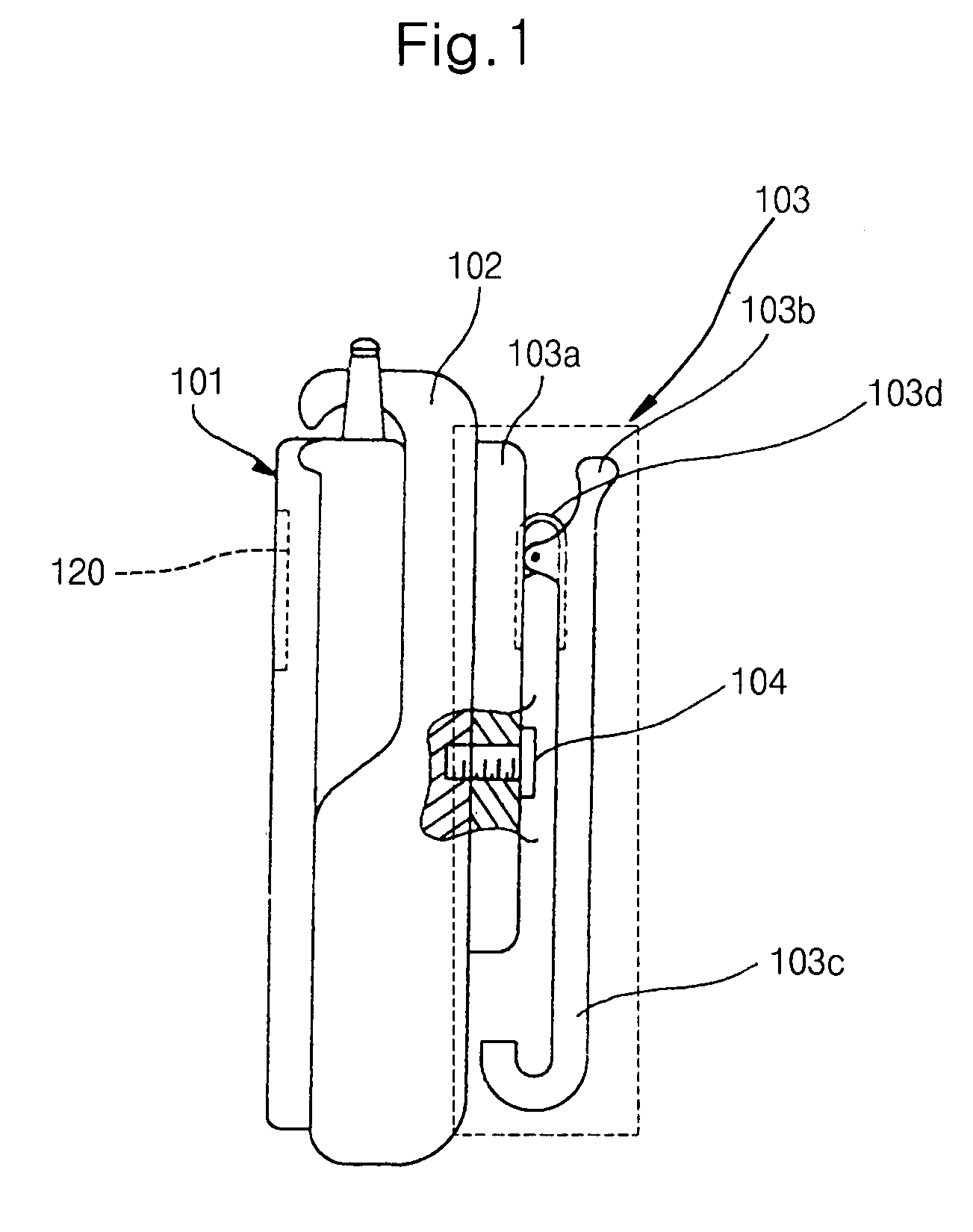
[0030]Referring to FIGS. 2 to 5, a belt clip device for a mobile communication terminal unit according to an embodiment of the present invention is illustrated, respectively. As shown in FIGS. 2 to 5, the belt clip device includes a terminal unit holder 202 for receiving and holding a terminal unit 201, a clamp 203 connected to the terminal unit holder 202 at one side of the terminal unit holder 202 and adapted to allow the belt clip device to be mounted to a belt, and a connecting means for rotatably connecting the clamp 203 to the terminal unit holder 202.

[0031]The clamp 203 has a panel-shaped base portion 203a, and a panel portion 203c hingably coupled at the upper end thereof to the base portion 203a. The panel portion 203c is provided at the upper end thereof with a depressing portion 203b and at the lower end thereof with a stopper. The depressing portion 203b a...


PUM


Abstract

A belt clip device is provided for a mobile communication terminal unit. The belt clip device includes a terminal unit holder for receiving and holding the terminal unit, a clamp provided on one side of the terminal unit holder and adapted to resiliently clip a belt worn by a user, thereby allowing the belt clip device to be mounted to the belt, and a connector for rotatably connecting the clamp to the terminal unit holder. The clamp includes a base portion, a panel portion hingably coupled at one end thereof to the base portion and spaced apart from the base portion to define a gap for receiving the belt therebetween, a spring adapted to urge the base portion and the panel portion in such a fashion that the gap is resiliently maintained, and a stopper provided at the other end of the panel portion and adapted to prevent the clamp from being separated from the belt. The connector includes a hinging member hingably coupled to the base portion of the clamp to hinge about a hinge shaft with respect to the clamp, and a rotating shaft for rotatably coupling the terminal unit holder to the hinging member in such a fashion that the terminal unit holder rotates about the rotating shaft with respect to the hinging member. By this configuration, the user can conveniently view a display window of the terminal unit without separating the terminal unit from the terminal unit holder.

Description

BACKGROUND OF THE INVENTION[0001]1. Field of the Invention[0002]The present invention relates to a belt clip device for a mobile communication terminal unit, and more particularly to a belt clip device for a mobile communication terminal unit capable of allowing the user to conveniently view the display window of the terminal unit even in a state wearing the terminal unit at his side.[0003]2. Description of the Prior Art[0004]Today, mobile communication systems has been rendered to be a necessity in the present society. This has resulted in an increased demand for terminal units of such mobile communication systems. Recently, terminal units having new functions have been developed in order to allow those terminal units to be more conveniently used. In particular, in mobile communication terminal units, the convenience in carrying those terminal units is considered to be important because they are always carried by user on their bodies.[0005]Typically, a mobile communication terminal...

Claims


Application Information

Patent Timeline
IPC IPC(8): H04M1/00
CPCH04B1/3888H04M1/04H04B2001/3855Y10T24/1388Y10T24/13
Inventor KIM, HONG JOOYANG, HAE SEOCK
Owner LG INFORMATION & COMM LTD
Learn More