Over-power protection apparatus for self-excited power converter

Active Publication Date: 2006-10-03
SEMICON COMPONENTS IND LLC
View PDF4 Cites 21 Cited by
  • Summary
  • Abstract
  • Description
  • Claims
  • Application Information

AI Technical Summary

Benefits of technology

[0022]An object of the present invention is to provide an over-power protection apparatus for self-excited power converter. The duty cycle of the upper and lower transistor is reduced

Problems solved by technology

A limited output power is thus required for a power converter under the overload and short circuit conditions.
The power switch of the power supply susta

Method used


Image

  • Over-power protection apparatus for self-excited power converter
  • Over-power protection apparatus for self-excited power converter
  • Over-power protection apparatus for self-excited power converter

Examples


Embodiment Construction

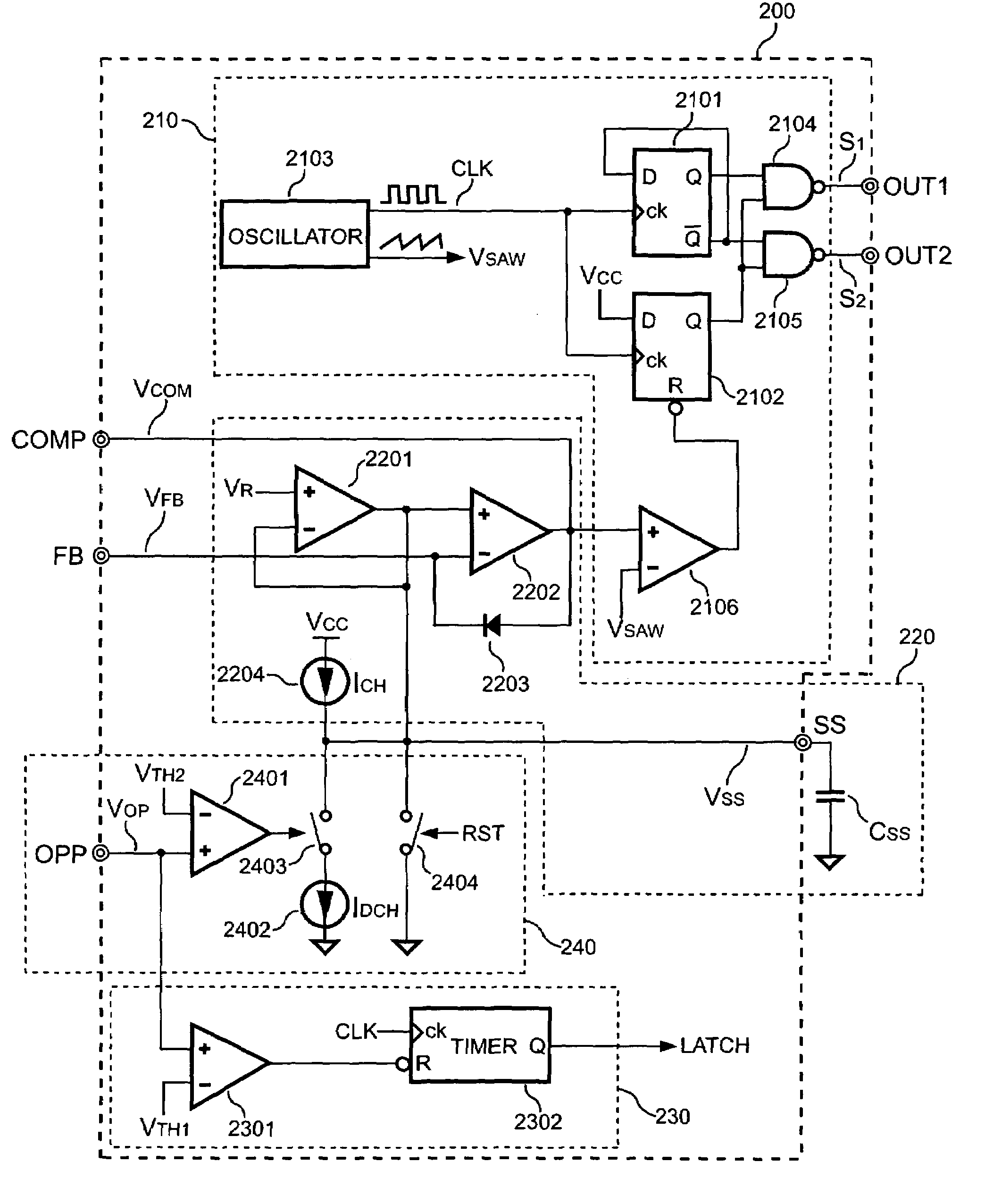
[0036]FIG. 5 shows a schematic diagram of a PWM controller of the self-excited power converter according to the present invention. An over-power protection apparatus is coupled to a PWM unit 210 of a PWM controller 200 and it can build-in or not build-in the PWM controller 200 of the self-excited power converter. The over-power protection apparatus in accordance with the present invention includes a soft-start unit 220, a timing unit 230 and an adjusting unit 240. The soft-start unit 220 consists of an operation amplifier 2201, an error amplifier 2202, a clamp diode 2203 and a charging unit that includes a first power source 2204 as well as a start-up capacitor CSS. The first power source 2204 is coupled to the start-up capacitor CSS for charging the start-up capacitor CSS.

[0037]The positive input of the operation amplifier 2201 receives a reference voltage VR. The negative input of the operation amplifier 2201 is coupled to the output of the operation amplifier 2201 and the start-u...


PUM


Abstract

An over-power protection apparatus for self-excited power converter comprises a soft-start unit, an adjusting unit and a timing unit. A PWM unit of the self-excited power converter generates a switching signal in response to a compensating signal of the soft-start unit to control the output power of the self-excited power converter. The soft-start unit couples to the adjusting unit. The adjusting unit drives the soft-start unit and the PWM unit for modulating the switching signal to reduce the pulse width of the switching signal and the output power of the self-excited power converter once the short-circuit and over-load are happened at the output of the self-excited power converter. In the meantime, a timing unit starts to count. The timing unit drives the self-excited power converter to stop supplying the power source after the counting and the over-power lasting for a period of time.

Description

BACKGROUND OF INVENTION[0001]1. Field of the Invention[0002]The present invention relates to an over-power protection circuit, and more specifically, to an over-power protection circuit for self-excited power converter.[0003]2. Description of Related Art[0004]Various self-excited power converters have been widely used in desktop computers for providing regulated voltage and current. The self-excited half-bridge power converter is a main application circuit in the field of the self-excited power converter. FIG. 1 illustrates the topology of a conventional self-excited half-bridge power converter composed of a primary-side circuit, a main transformer T1, a secondary-side circuit, an over-power detecting circuit and a driving transformer T2. The primary-side circuit comprises a regulating capacitor C1, a regulating capacitor C2, an upper power transistor Q3, an upper driving circuit 32, a lower power transistor Q4, a lower driving circuit 42 and a blocking capacitor CB. The secondary-s...

Claims


Application Information

Patent Timeline
IPC IPC(8): H02M3/335H02H7/122H02M7/538
CPCH02H7/1227H02M3/3382
Inventor YANG, TA-YUNG
Owner SEMICON COMPONENTS IND LLC
Why Eureka
Try Eureka