Multi-phase DC-DC converter and control circuit for multi-phase DC-DC converter

a control circuit and converter technology, applied in the field of converters, can solve the problems of increasing the switching frequency of the output transistor, the operation efficiency of the output transistor decreases, and the dc—dc converter b>100/b> has a poor responsiveness to a sudden change in load, so as to improve the load responsiveness of the converter, the operating efficiency of the output transistor decreases, and the converter is easy to opera

Active Publication Date: 2006-10-17
CYPRESS SEMICON CORP
View PDF6 Cites 20 Cited by
  • Summary
  • Abstract
  • Description
  • Claims
  • Application Information

AI Technical Summary

Problems solved by technology

Thus, the DC—DC converter 100 has a problem of poor responsiveness to a sudden change in the load.
However, if the switching cycle of the output transistor is further shortened, the operating efficiency of the output transistor decreases due to a gate capacity of the output transistor.
Thus, increasing the switching frequency of the output transistor fails to sufficiently improve the load responsiveness of the converter.
However, the timing at which the output transistor is turned on is not fixed.
Thus, the DC—DC converter 200 fails to execute multi-phase control of changing the switching timing (phase) of each of a plurality of DC—DC converters connected in parallel.

Method used


Image

  • Multi-phase DC-DC converter and control circuit for multi-phase DC-DC converter
  • Multi-phase DC-DC converter and control circuit for multi-phase DC-DC converter
  • Multi-phase DC-DC converter and control circuit for multi-phase DC-DC converter

Examples


first embodiment

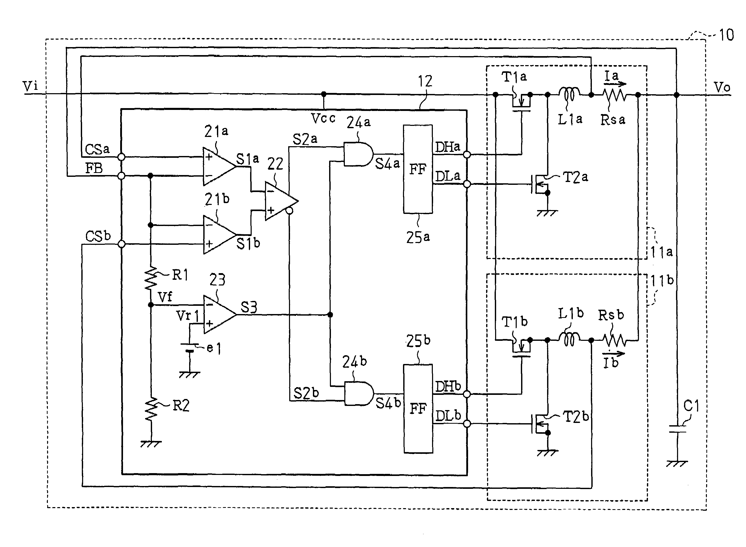
[0044]FIG. 4 is a schematic circuit diagram of a multi-phase DC—DC converter 10 according to the present invention.

[0045]The DC—DC converter 10 is a self-excited multi-phase DC—DC converter having two phases. The DC—DC converter 10 includes two converter units 11a and 11b, one control unit 12, and a smoothing capacitor C1.

[0046]The first converter unit 11a includes an output transistor T1a, a synchronous rectifier transistor T2a, a choke coil Lla, and a current detection resistor Rsa. The output transistor T1a is configured by an N-channel MOS transistor. The synchronous rectifier transistor T2a is configured by an N-channel MOS transistor. The output transistor T1a has a gate for receiving a control signal DHa from the control unit 12, a drain for receiving an input voltage Vi, and a source connected to the synchronous rectifier transistor T2a. The synchronous rectifier transistor T2a has a gate for receiving a control signal DLa from the control unit 12, a drain connected to the o...

second embodiment

[0069]FIG. 5 is a schematic circuit diagram of a multi-phase DC—DC converter 30 according to the present invention.

[0070]The DC—DC converter 30 is a self-excited multi-phase DC—DC converter having two phases. The DC—DC converter 30 includes two converter units 11a and 11b, one control unit 32, and a smoothing capacitor C1.

[0071]The control unit 32 includes two voltage amplifiers 21a and 21b, a comparator 22, two voltage comparators 23a and 23b, two reference power supplies e1 and e2, two resistors R1 and R2, two AND circuits 24a and 24b, two one-shot flip-flop circuits (hereafter referred to as “FF circuits”) 25a and 25b, and two OR circuits 26a and 26b. The control unit 32 of the second embodiment has a configuration in which the voltage comparator 23b, the reference power supply e2, and the OR circuits 26a and 26b are added to the control unit 12 of the first embodiment.

[0072]The first voltage comparator 23a operates substantially in the same manner as the voltage comparator 23 of...

third embodiment

[0079]FIG. 6 is a schematic circuit diagram of a multi-phase DC—DC converter 40 according to the present invention.

[0080]The DC—DC converter 40 is a self-excited multi-phase DC—DC converter having three phases. The DC—DC converter 40 includes three converter units 11a, 11b, and 11c, one control unit 42, and a smoothing capacitor C1.

[0081]Each of the converter units 11a to 11c has the same configuration. The first converter unit 11a includes an output transistor T1a, a synchronous rectifier transistor T2a, a choke coil L1a, and a current detection resistor Rsa. The output transistor T1a is configured by an N-channel MOS transistor. The synchronous rectifier transistor T2a is configured by an N-channel MOS transistor. The second converter unit 11b includes an output transistor T1b, a synchronous rectifier transistor T2b, a choke coil L1b, and a current detection resistor Rsb. The output transistor T1b is configured by an N-channel MOS transistor. The synchronous rectifier transistor T...


PUM


Abstract

A self-excited multi-phase DC—DC converter having satisfactory responsiveness when its load suddenly changes. A control unit of the converter compares output currents of first and second converter units. Based on the comparison result, the control unit generates control signals to operate a converter unit through which a smaller output current flows. For example, when an output voltage of the converter decreases due to a sudden change in the load while the first converter unit is operating to supply current, the second converter unit through which a smaller output current flows is operated to increase the output voltage.

Description

CROSS-REFERENCE TO RELATED APPLICATIONS[0001]This application is based upon and claims the benefit of priority from the prior Japanese Patent Application No. 2005-020141, filed on Jan. 27, 2005, the entire contents of which are incorporated herein by reference.BACKGROUND OF THE INVENTION[0002]The present invention relates to a converter, and more particularly, to a multi-phase DC—DC converter and a control circuit for a multi-phase DC—DC converter.[0003]Japanese Laid-Open Patent Publication Nos. 2000-308337, 2002-044941, and 2003-284333 each describe an example of a conventional multi-phase DC—DC converter, in which a plurality of DC—DC converters are connected in parallel and each converter is operated at a different switch timing (phase).[0004]Methods for controlling a DC—DC converter include separate-excitation and self-excitation. With separate-excitation, a DC—DC converter performs a switching operation in synchronization with a clock signal (separately-excited DC—DC converter)...

Claims


Application Information

Patent Timeline
Patent Type & Authority Patents(United States)
IPC IPC(8): G05F1/618
CPCH02M3/1584
Inventor HASEGAWA, MORIHITOOZAWA, HIDEKIYO
Owner CYPRESS SEMICON CORP
Why Eureka
Try Eureka