Integrated magnetics for a DC-DC converter with flexible output inductor

a technology of integrated magnetics and dc converters, which is applied in the direction of electric variable regulation, process and machine control, instruments, etc., can solve the problems of affecting the efficiency and reliability of the converter, the inability of the transformer to provide output voltage and current directly to a load in a regulated manner, and the cost of the magnetic components of a typical dc—dc converter. to achieve the effect of optimizing the design of the inductor and the transformer

Inactive Publication Date: 2006-04-25
NORTHEASTERN UNIV
View PDF18 Cites 110 Cited by
  • Summary
  • Abstract
  • Description
  • Claims
  • Application Information

AI Technical Summary

Benefits of technology

[0013]This integration of the primary and secondary windings and the inductor winding on the unitary magnetic structure advantageously decouples the inductor function from the transformer function and allows the more opti...

Problems solved by technology

The magnetic components of a typical DC—DC converter are often expensive, usually the physically largest, and often very significantly affect the efficiency and reliability of the converter.
However, because the input voltage is typically switched at a high frequency the output voltage and current from the transformer cannot be directly provided to a load in a regulated manner.
However, often the integrated magnetics of the prior art do not have an inductor winding because the windings of the transformer, particularly the secondary winding of the transformer, provides the necessary inductance during the magnetic energy discharge operating stage.
Often times the minimum required inductance requires...

Method used


Image

  • Integrated magnetics for a DC-DC converter with flexible output inductor
  • Integrated magnetics for a DC-DC converter with flexible output inductor
  • Integrated magnetics for a DC-DC converter with flexible output inductor

Examples


Embodiment Construction

[0031]The U.S. Provisional Application No. 60 / 328,987 titled Integrated Magnetic Full Wave Converter with Flexible Output Inductor, filed Oct. 12, 2001 is hereby incorporated by reference.

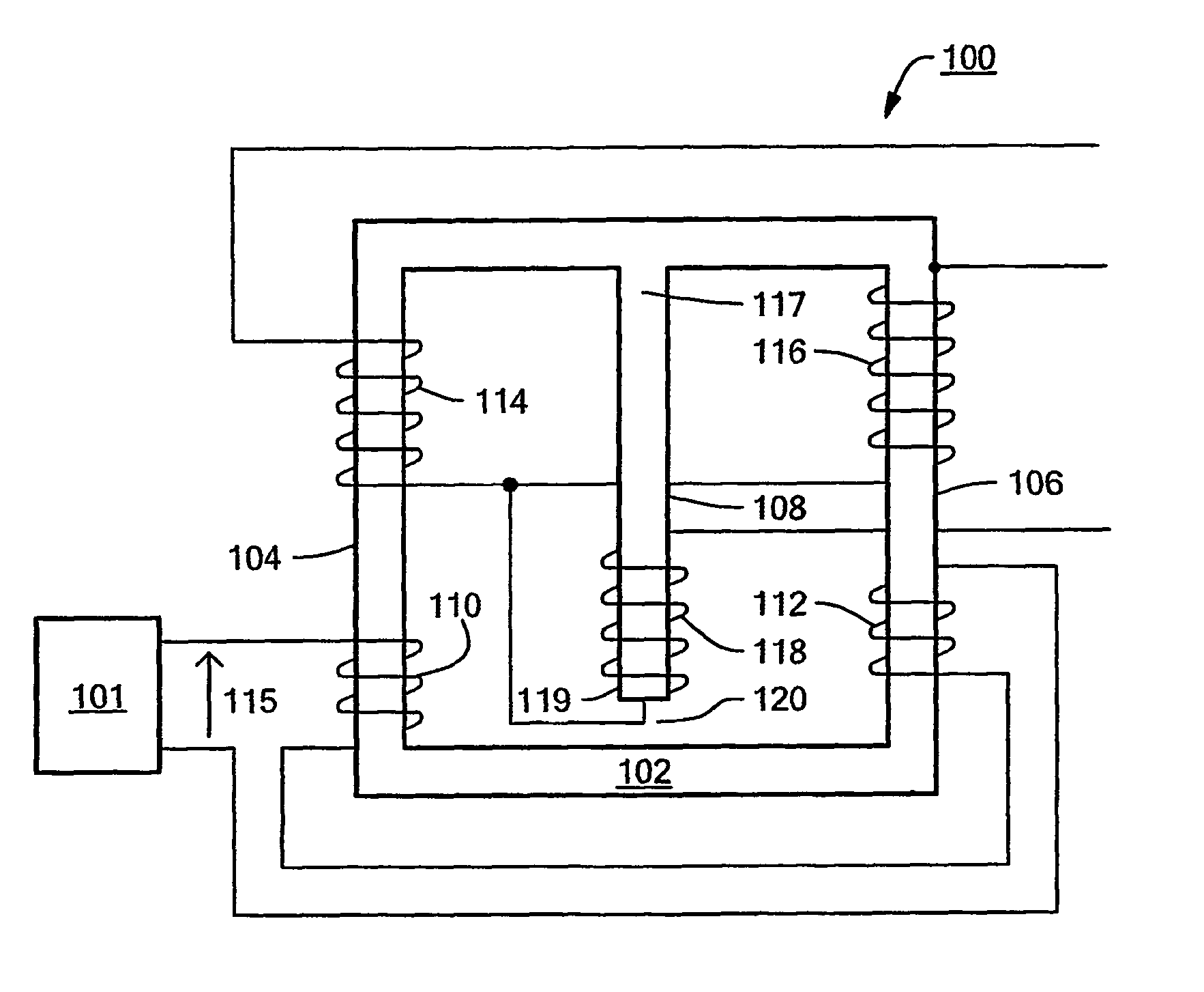
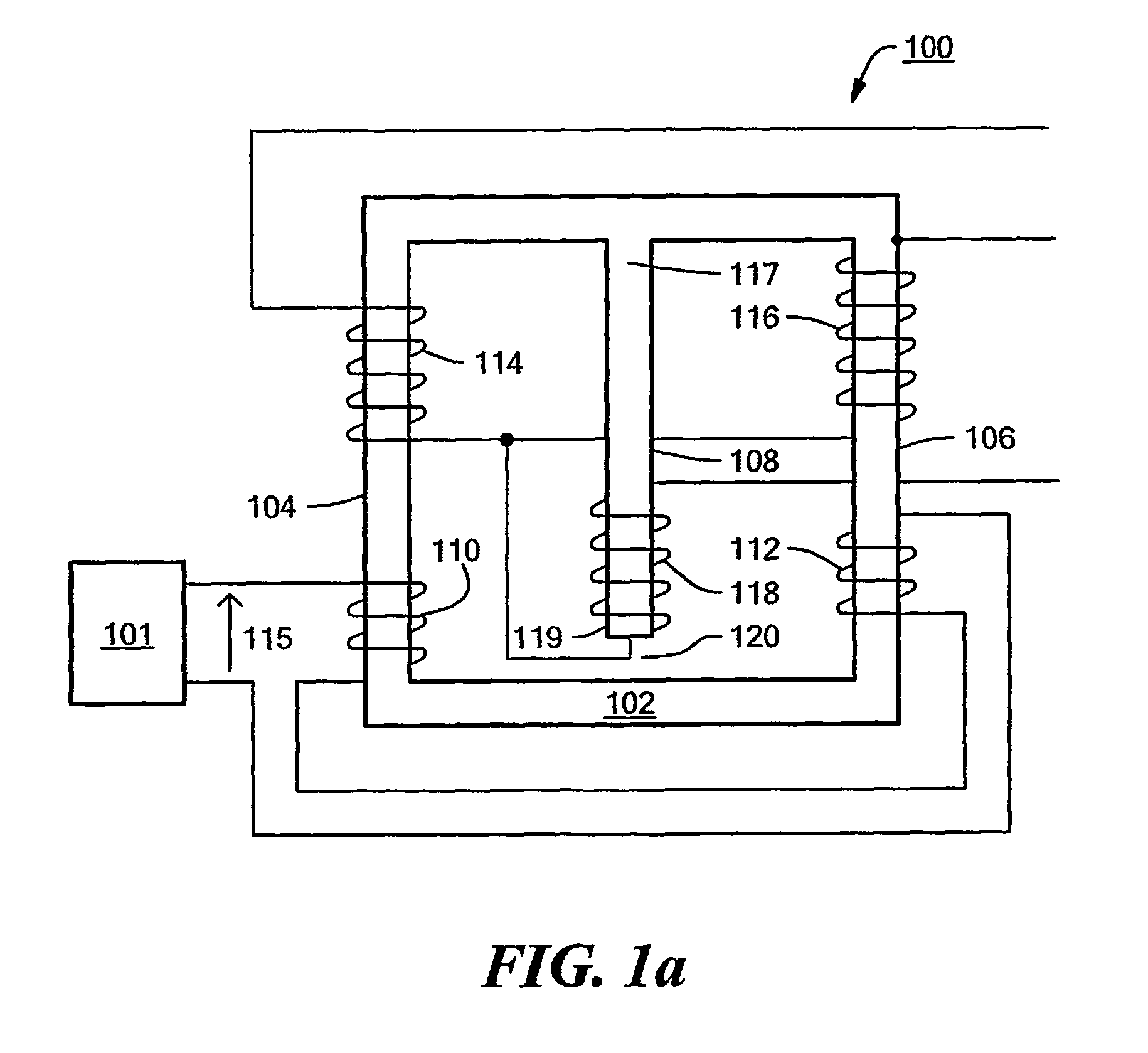
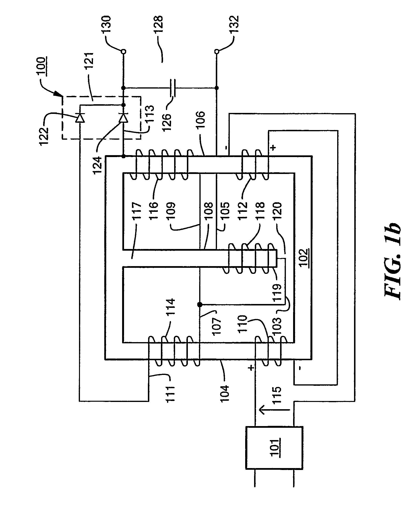
[0032]An integrated magnetic assembly for use as a transformer that allows the primary and secondary transformer windings, and an inductor winding to be integrated on a unitary magnetic structure is disclosed. The integrated magnetic structure described herein includes a unitary magnetic structure having three legs and a primary and secondary winding disposed on one or more of the three legs. A separate inductor winding on one or more of the three legs of the unitary magnetic structure is also provided for. This configuration advantageously decouples the inductor function from the secondary winding of the transformer and allows both the inductor and the transformer to be more optimally designed. With the addition of a pair of rectifiers, the integrated magnetic assembly may be configured with a f...


PUM


Abstract

An integrated magnetic assembly that allows the primary and secondary windings of a transformer and a separate inductor winding to be integrated on a unitary magnetic structure is disclosed. The unitary magnetic structure includes first, second, and third legs that are physically connected and magnetically coupled. The primary and secondary windings of the transformer can be formed on the third leg of the unitary magnetic structure. Alternatively, the primary and secondary windings can be split between the first and second legs. Thus, the primary winding includes first and second primary windings disposed on the first and second legs and the secondary winding includes first and second secondary windings disposed on the first and second legs. The inductor winding may also be formed either on the third leg or it may split into first and second inductor windings and disposed on the first and second legs. In addition, one or more legs may include an energy storage component such as an air gap. This integration of the primary and secondary windings and the inductor winding on the unitary magnetic structure advantageously decouples the inductor function from the transformer function and allows the more optimal design of both the inductor and the transformer. The unitary magnetic structure may be coupled to a full bridge, a half bridge, or a push pull voltage input source to form a DC—DC converter.

Description

CROSS REFERENCE TO RELATED APPLICATIONS[0001]The present application claims priority under 35 USC §119(e) of U.S. Provisional Application No. 60 / 328,987 titled Integrated Magnetic Full Wave Converter with Flexible Output Inductor, filed Oct. 12, 2001.STATEMENT REGARDING FEDERALLY SPONSORED RESEARCH OR DEVELOPMENT[0002]N / ABACKGROUND OF THE INVENTION[0003]DC—DC converters are used to convert an input DC voltage into a different output DC voltage having a larger or smaller magnitude, possibly with the opposite polarity or with isolation of the input and the output ground references. Contemporary DC—DC converters should provide a high power density and a high efficiency at a minimum price and high efficiency. The magnetic components of a typical DC—DC converter are often expensive, usually the physically largest, and often very significantly affect the efficiency and reliability of the converter.[0004]DC—DC converters accept input energy from a voltage source at an input voltage and cur...

Claims


Application Information

Patent Timeline
IPC IPC(8): H01F27/24H02M3/335H01F27/38H01F37/00H02M3/337
CPCH01F27/38H01F37/00H02M3/337H02M3/33523H01F2038/026H02M3/33573H02M3/33571
Inventor YAN, LIANGQU, DAYULEHMAN, BRADLEY
Owner NORTHEASTERN UNIV
Why Eureka
Try Eureka