Fuel cell based rechargable power pack system and associated methods for controlling same

Inactive Publication Date: 2007-08-16
MTI MICROFUEL CELLS
View PDF11 Cites 115 Cited by
  • Summary
  • Abstract
  • Description
  • Claims
  • Application Information

AI Technical Summary

Benefits of technology

[0018] In each of the embodiments, a battery protection and power pack control circu

Problems solved by technology

However, such power sources may not be available and a portable recharging device is required.
Rechargeable batteries would thus be encouraged; however, a person can not be assured that they would remain charged and would be ready at all times. A powe

Method used


Image

  • Fuel cell based rechargable power pack system and associated methods for controlling same
  • Fuel cell based rechargable power pack system and associated methods for controlling same
  • Fuel cell based rechargable power pack system and associated methods for controlling same

Examples


Embodiment Construction

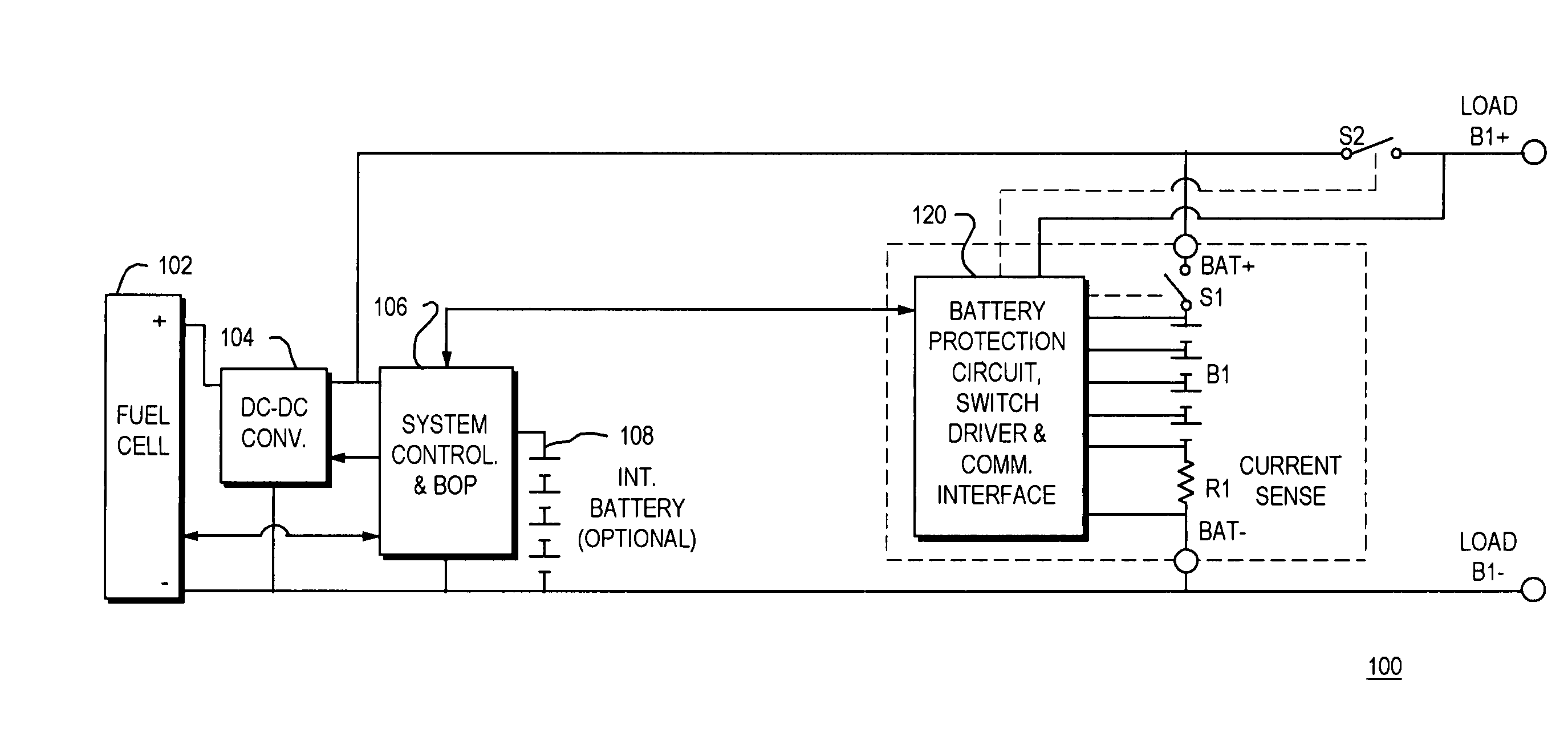
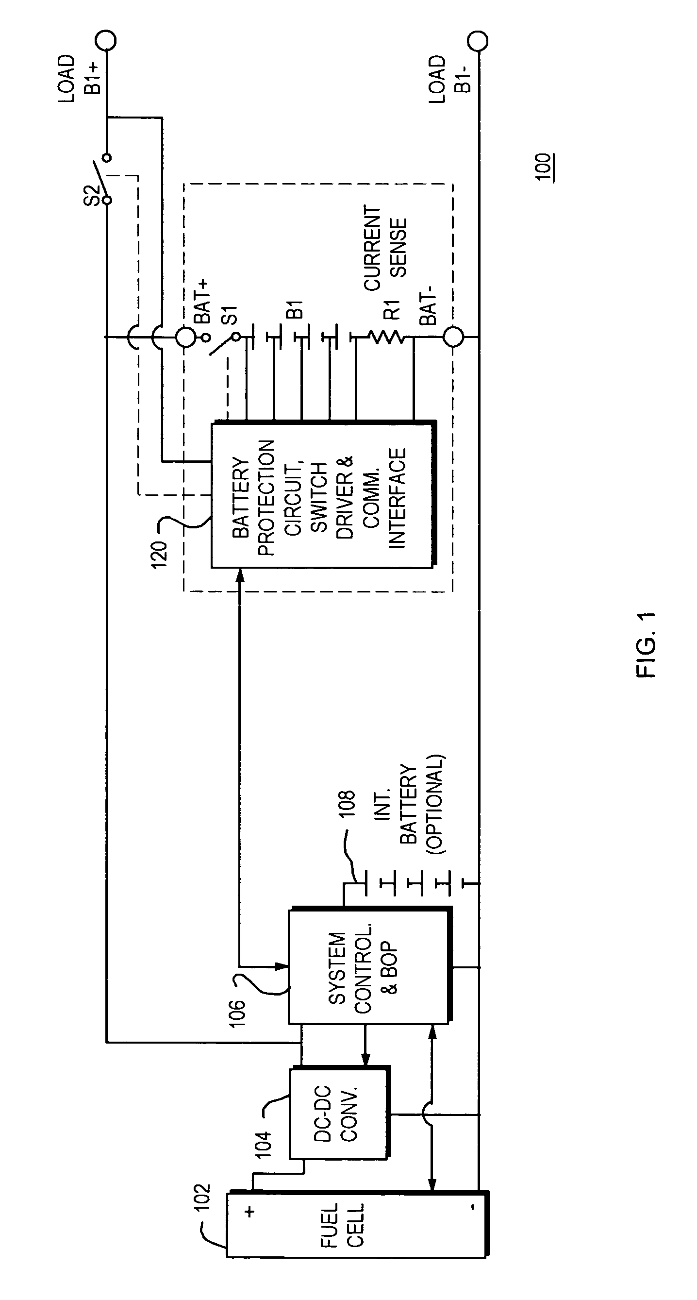
[0036]FIG. 1 is a schematic block diagram of a fuel-cell battery power pack with a single battery output that makes use of a battery protection circuit modified to allow the system controller to turn the switches on and off during non-fault conditions in accordance with an illustrative embodiment of the present invention. More specifically, FIG. 1 illustrates a power pack 100 that includes a fuel cell 102, a DC-DC converter 104 and a system controller and balance of plant 106, which is powered either by the optional internal battery 108 or the main battery B1. As noted, the system controller and balance of plant 106 includes items such as the fans, pumps, valves, and sensors necessary to operate the fuel cell 102. A rechargeable battery B1 with a battery protection circuit 120 and a load disconnect switch S2, as well as the DC-DC converter 104 are controlled in the manner described in the above-cited U.S. Pat. No. 6,590,370.

[0037] In operation, the output voltage of a fuel cell 102...


PUM


Abstract

A power pack system for charging a set of isolated batteries is provided. In an illustrative embodiment of the invention, a single fuel cell, a single DC-DC converter and a single system controller device comprises the power-generation side of the power pack. A set of switches is used to connect the power-generation side of the Power pack to one of the isolated batteries in the power pack, thereby recharging that particular battery in the battery power pack set. A battery protection and powerpath control device communicates with the system controller to determine which switches are to be closed depending upon which battery requires recharging. During normal operation the switches will follow the direction from the system controller. If a fault is detected by the battery protection circuit, the protection circuit will take priority and turn off the appropriate switch(es).

Description

BACKGROUND OF THE INVENTION [0001] 1. Field of the Invention [0002] This invention relates to fuel cell systems that include fuel cells and rechargeable batteries for various power needs. [0003] 2. Background Information [0004] Many electrically powered devices, including commercial and military applications require a reliable battery with high-energy density and long life. There are numerous conventional techniques and components for charging rechargeable batteries such as lithium ion batteries which are widely used in both consumer and military electronic applications. Typically an A / C wall outlet or a 12 volt DC source commonly provided in vehicles can be used for a power source for such recharging. However, such power sources may not be available and a portable recharging device is required. [0005] Use of a fuel cell in the power source for use as a battery recharger for a battery which is powering a portable device has been described in commonly owned U.S. Pat. No. 6,590,370, o...

Claims


Application Information

Patent Timeline
IPC IPC(8): H01M16/00H01M8/04H01M10/42H01M10/46
CPCH02J7/0018H02J7/0019H02J7/0026H02J2007/004H02J2001/004H02J2007/0037H02J7/34H02J7/00306H02J2300/30H02J7/00302H02J7/00308H02J7/00304
Inventor LEACH, DAVID H.MARVIN, RUSSEL
Owner MTI MICROFUEL CELLS
Why Eureka
Try Eureka