Electric power steering system

a technology of electric power steering and steering wheel, which is applied in the direction of steering initiation, instruments, vessel construction, etc., can solve the problems of vibration in the steering, the abnormality of the torque sensor caused by other factors may not be detected, etc., and achieve the effect of suppressing the occurrence of unintended steering behavior

Active Publication Date: 2014-06-26
JTEKT CORP
View PDF7 Cites 23 Cited by
  • Summary
  • Abstract
  • Description
  • Claims
  • Application Information

AI Technical Summary

Benefits of technology

[0009]The invention provides an electric power steering system in wh

Problems solved by technology

However, since the EPS in JP 2006-248354 A detects the abnormality of the torque sensor on the basis of the amount of fluctuation of the sensor signal, the abnormality of the torque sensor caused by other factors may not be detected

Method used


Image

  • Electric power steering system
  • Electric power steering system
  • Electric power steering system

Examples


first embodiment

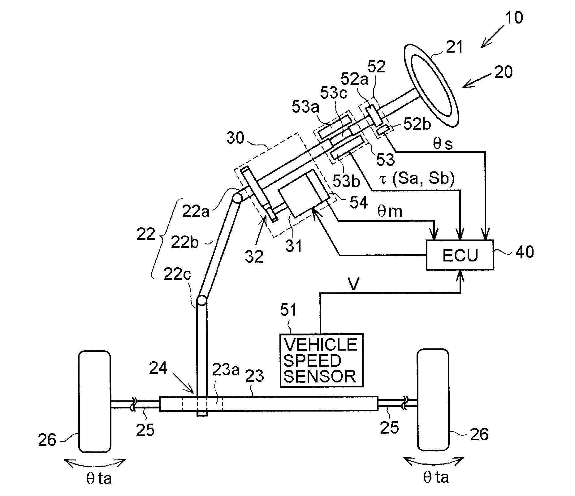
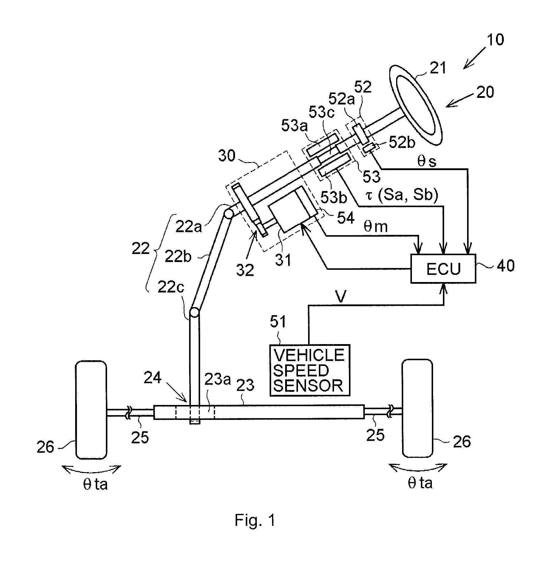
[0024]An electric power steering system will be described below with reference to FIGS. 1 to 7. As shown in FIG. 1, an electric power steering system (EPS) 10 includes a steering mechanism 20 that causes steered wheels to be steered on the basis of a steering operation performed by a driver, a steering assist mechanism 30 that assists the steering operation performed by the driver, and an electronic control unit (ECU) 40 that controls the operation of the steering assist mechanism 30.

[0025]The steering mechanism 20 includes a steering wheel 21 operated by the driver, and a steering shaft 22. The steering shaft 22 includes a column shaft 22a, an intermediate shaft 22b, and a pinion shaft 22c. A lower end portion of the pinion shaft 22c meshes with a rack shaft 23 (rack teeth 23a) that extends in a direction intersecting the pinion shaft 22c. A rotational motion of the steering shaft 22 is converted to a reciprocating linear motion of the rack shaft 23 by a rack and pinion mechanism ...

second embodiment

[0112]In the second embodiment, in the determination of Step S603 in the flowchart of FIG. 10, the steering speed cos is compared with the steering speed determination threshold ωsh. However, the steering speed determination threshold ωsh may be made different from the value used in the steering speed gain map 85.

[0113]In each of the above-described embodiments, the assist control unit 72 may execute various kinds of compensation control, for example, torque differentiation control. In this case, the assist control unit 72 calculates a compensation component (torque differentiation controlled variable) based on a differential value of the steering torque τ, and adds the compensation component to the basic assist controlled variable Ias*. This enhances a response with which the assist force is applied with respect to a change in the steering torque τ. Note that when the above-described so-called reverse gain failure has occurred, the plus or minus sign of the compensation component i...


PUM


Abstract

When a steering speed reaches a steering speed determination threshold, a steering speed gain is set to “0”. As a result, a final basic assist controlled variable becomes “0”, and application of an assist force to a steering system is stopped. Therefore, repetition of so-called reverse assist that is a cause of occurrence of an unintended steering behavior, such as self-excited vibration, is stopped. Accordingly, the steering behavior is improved.

Description

INCORPORATION BY REFERENCE / RELATED APPLICATION[0001]This application claims priority to Japanese Patent Application No. 2012-281519 filed on Dec. 25, 2012 the disclosure of which, including the specification, drawings and abstract, is incorporated herein by reference in its entirety.BACKGROUND OF THE INVENTION[0002]1. Field of the Invention[0003]The invention relates to an electric power steering system.[0004]2. Discussion of Background[0005]Generally, electric power steering systems (EPSs) include a motor as a drive source, a torque sensor, and a control device. The torque sensor generates a sensor signal on the basis of twisting of a torsion bar provided in the intermediate portion of a steering shaft. The control device detects a steering torque on the basis of the sensor signal and controls the torque of the motor so that a suitable assist force is applied to a steering system according to the steering torque. Therefore, in the EPS, in order to obtain the suitable assist force, ...

Claims


Application Information

Patent Timeline
IPC IPC(8): B62D5/04
CPCB62D5/049B62D5/0484B62D5/0463B62D6/00
Inventor ITAMOTO, HIDENORINAKASONE, GEMPEIMITSUHARA, TAKASHIIKENO, MAKOTO
Owner JTEKT CORP
Why Eureka
Try Eureka