Belt tensioner for electric power steering unit

a technology of electric power steering and belt tensioner, which is applied in the direction of gear, cycle equipment, guards, etc., can solve the problems of slipping relative, and affecting the operation of the bel

Inactive Publication Date: 2005-11-01
TRW INC
View PDF18 Cites 71 Cited by
  • Summary
  • Abstract
  • Description
  • Claims
  • Application Information

AI Technical Summary

Problems solved by technology

Rotation of the steering wheel to adequately turn the vehicle may be difficult depending on various factors, such as the speed of the vehicle and the mechanical coupling of the steering system.
Although the use o

Method used


Image

  • Belt tensioner for electric power steering unit
  • Belt tensioner for electric power steering unit
  • Belt tensioner for electric power steering unit

Examples


first embodiment

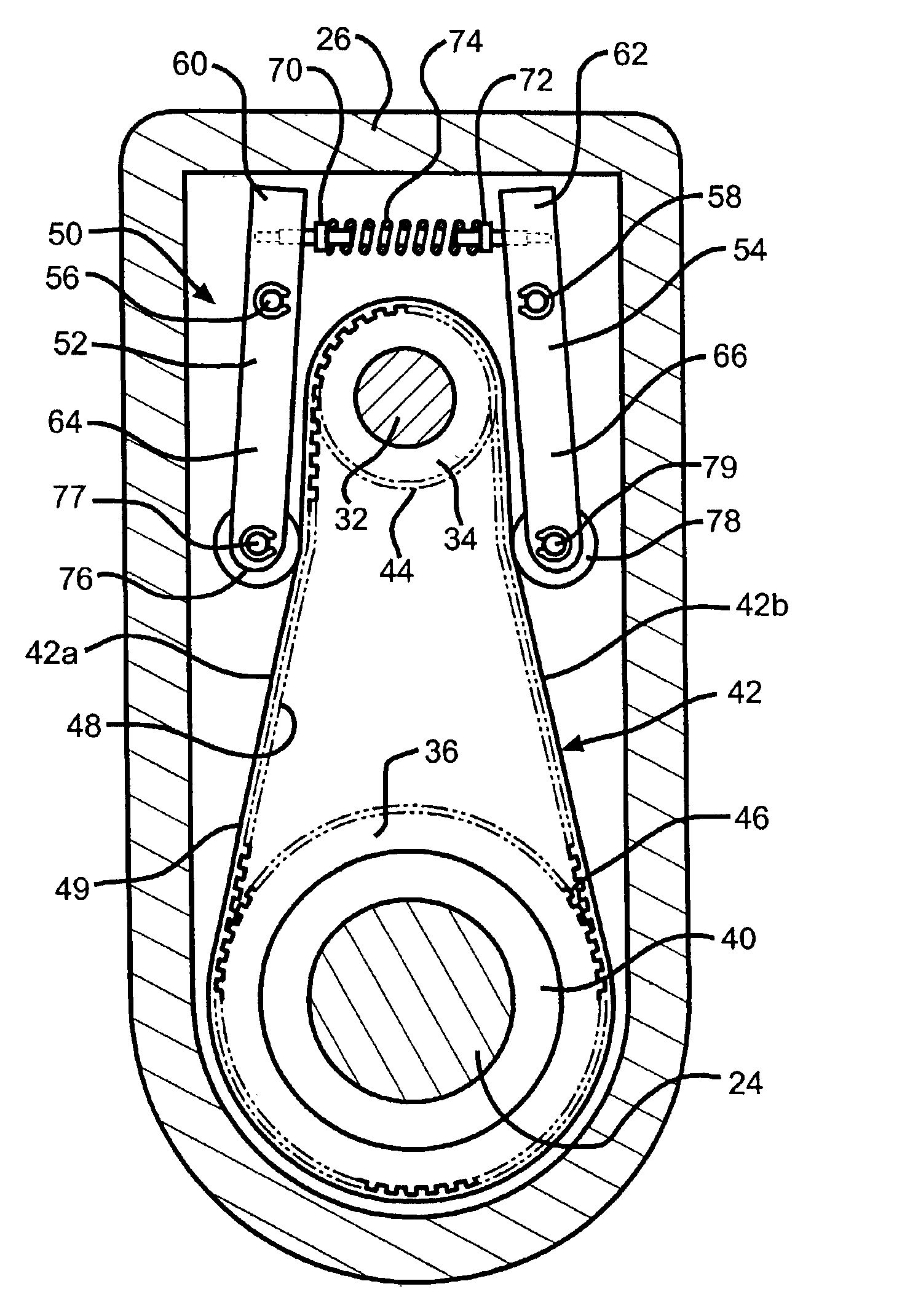
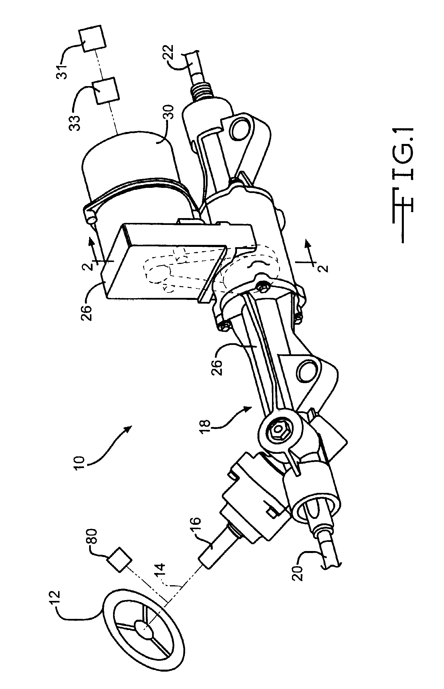
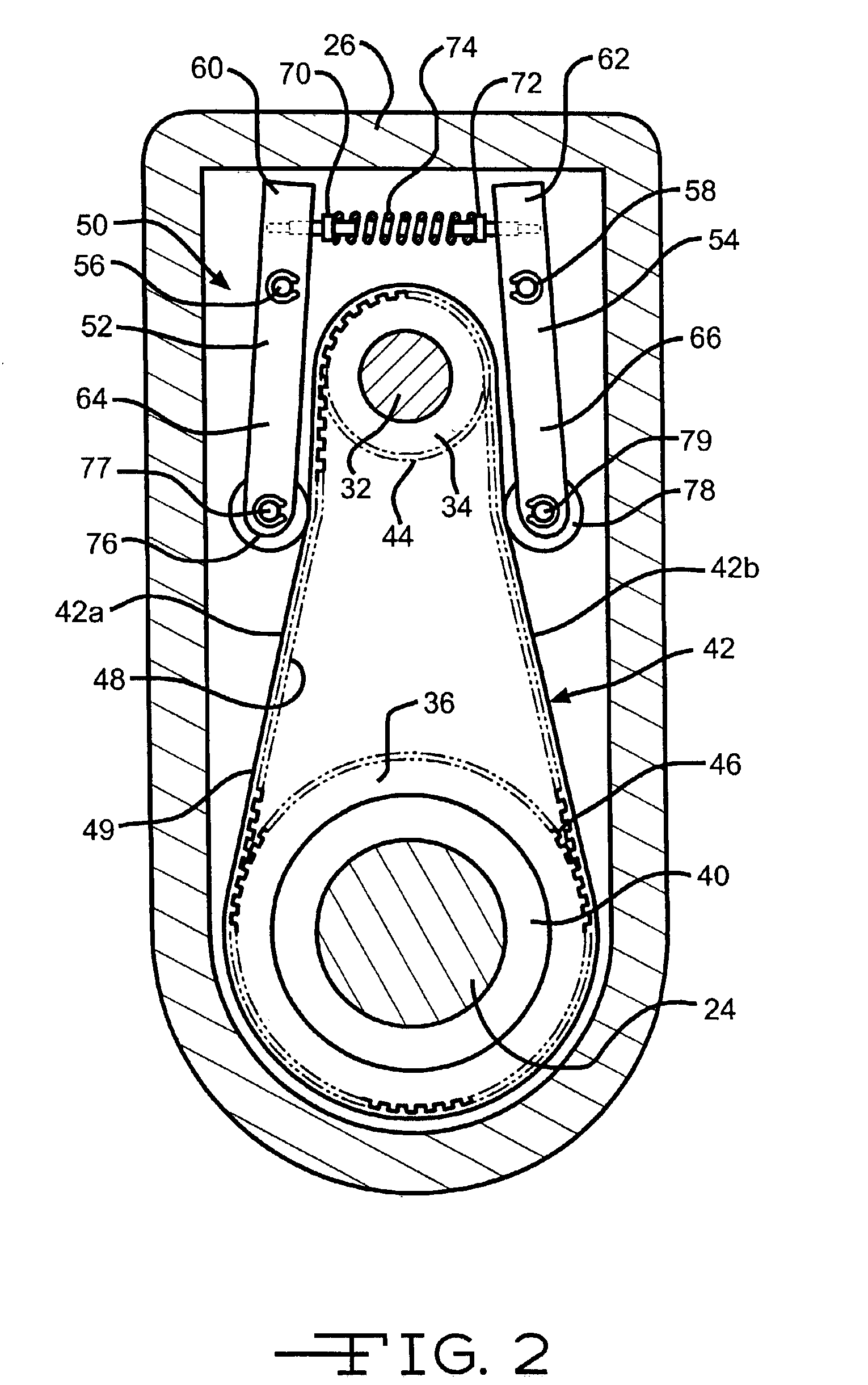
[0018]The system 10 preferably further includes a tensioner, indicated generally at 50, in accordance with the present invention. The tensioner 50 preferably includes a pair of arms 52 and 54. The arms 52 and 54 are pivotally mounted on the housing 26 of the steering gear assembly 18 by pivot pins 56 and 58, respectively. The pivot pins 56 and 58 define pivot axes about which the arms pivot relative to the housing 26. Each arm 52 and 54 includes an upper portion 60 and 62, respectively, and lower portions 64 and 66, respectively, separated by the pivot pins 56 and 58. Each of the upper portions 64 and 66 include a retainer pin 70 and 72, respectively, extending toward one another. A helical coil spring 74 extends between the upper portions 60 and 62. The ends of the spring 74 are retained by the retainer pins 70 and 72. The coil spring 74 is under a compressive load and exerts a force against the retainer pins 70 and 72 in a direction towards the upper portions 60 and 62. As viewing...

second embodiment

[0024]It should also be understood that instead of using a single spring 74 to bias both of the arms 52 and 54, two separate springs could be used. Furthermore, any suitable spring structure can be used for biasing the arms 52 and 54 into a position such that the contact device abuts against the belt 42 to provide tension on the belt 42. For example, there is illustrated in FIGS. 3 and 4 a tensioner, indicated generally at 150 having a single coil spring 174. The tensioner 150 is similar in function to the tensioner 50 as shown in FIG. 2, and as such, similar 100 series and 10 series numbers indicate similar features.

[0025]The tensioner 150 includes a pair of inverted L-shaped arms 152 and 154. The arms 152 and 154 are pivotally mounted on the housing 26 by a common pivot pin 156. Thus, the arms 152 and 154 are pivotally mounted relative to the housing 26 at the same pivoting axis. The pin 156 is preferably fixed relative to the housing 26. The arms 152 and 154 include rollers 176 a...


PUM


Abstract

The invention relates to a tensioning device for use in vehicle power steering assembly, in particular, having a drive unit for rotating an input pulley rotatably connected to an output pulley via a flexible belt. The tensioning device includes a housing and an arm movably attached relative to the housing. A contact device is mounted on the arm and is adapted to be engaged with a portion of the belt between the input and output pulleys. The arm is movable relative to the belt to position the contact device against the belt to provide tension on the belt.

Description

BACKGROUND OF THE INVENTION[0001]This invention relates in general to vehicle power steering systems, and in particular to a belt tensioner for use with an electric power steering system.[0002]Virtually all vehicles include steering systems in which the driver of the vehicle turns the vehicle wheels via rotation of a steering wheel. Sometimes, rotation of the steering wheel rotates a steering column which is connected to a steering gear assembly. The steering gear assembly is coupled to the vehicle wheels. Rotation of the steering wheel to adequately turn the vehicle may be difficult depending on various factors, such as the speed of the vehicle and the mechanical coupling of the steering system. Therefore, many vehicles include power assisted steering systems which assist the driver in steering the vehicle.[0003]One traditional steering system includes hydraulic components, such as valves and cylinders, which apply a hydraulic force to the steering gear assembly to assist in turnin...

Claims


Application Information

Patent Timeline
IPC IPC(8): B62D5/04F16H7/12F16H7/08
CPCB62D5/0424F16H7/1281F16H2007/0806F16H2007/081F16H2007/0874
Inventor FRALEY, JR., RICHARD R.BUGOSH, MARK JOSEPHKONIOR, WILLIAM ALBERT
Owner TRW INC
Why Eureka
Try Eureka