

Motor drive and electric power steering apparatus using the same
a technology of electric power steering and motor drive, which is applied in the direction of motor/generator/converter stopper, dynamo-electric converter control, pulse technique, etc., can solve the problems of motor drive apparatus being likely to be damaged, inverter in normal power supply system overheating, sudden changes in operation, etc., and achieve the effect of reducing the change of operation
- Summary
- Abstract
- Description
- Claims
- Application Information
AI Technical Summary
Benefits of technology
Problems solved by technology
Method used
Image

Examples
first embodiment
[0040]The motor drive apparatus according to the first embodiment is shown in detail in FIGS. 4 to 6.
[0041]In FIG. 4, two power supply systems of as many as N power supply systems of the motor drive apparatus are shown exemplarily as the first power supply system and the second power supply system. N is an integer equal to or greater than 2. First and the second electric power control units 101 and 102 are provided for controlling the first and the second inverters 601 and 602, which supply electric power to the motor winding sets 801 and 802, respectively. The first power control unit 101 in the first power supply system includes a first current control unit 201 for the first inverter 601. The second power control unit 102 in the second power supply system includes a second current control unit 202 for the second inverter 602.
[0042]In case of N being equal to or greater than 3, more sets of electric power control units may be provided in parallel to the first and the second current...
second embodiment
[0058]The motor drive apparatus according to the second embodiment has the same hardware configuration as the first embodiment (FIG. 4). That is, as many as N current control units are provided. However, it is configured to operate differently in part from the first embodiment.
[0059]Specifically, the motor drive apparatus performs the failure-time current command value calculation as shown in FIG. 7 in a case that two current control sections are provided. At S21, it is checked whether the first power supply system is normal (F1=OFF) and the second power supply system is normal (F2=OFF). If the check result is YES, the q-axis current command value IQref is maintained as it is at S22. If the check result is NO, S23 is executed.
[0060]At S23, it is checked whether the first power supply system is in failure (F1=ON) and the second power supply system is normal (F2=OFF). If the check result at S23 is YES, the q-axis current command value IQref is doubled at S24. If the check result at S2...
third embodiment
[0077]The motor drive apparatus according to the third embodiment is shown in FIGS. 11, 12 and 13. In this embodiment, as shown in FIG. 12, power control units for supplying electric power to the motor winding set 801 of the first power supply system and the motor winding set 802 of the second power supply system is integrated into one power control unit 10.
[0078]The power control unit 10 includes one current control unit 20 and two inverters 601 and 602. In case of as many as N power supply systems, in which N is equal to or greater than 3, as many as N inverters 601, 602 and the like are provided in the power control unit 10 with one current control unit 20.
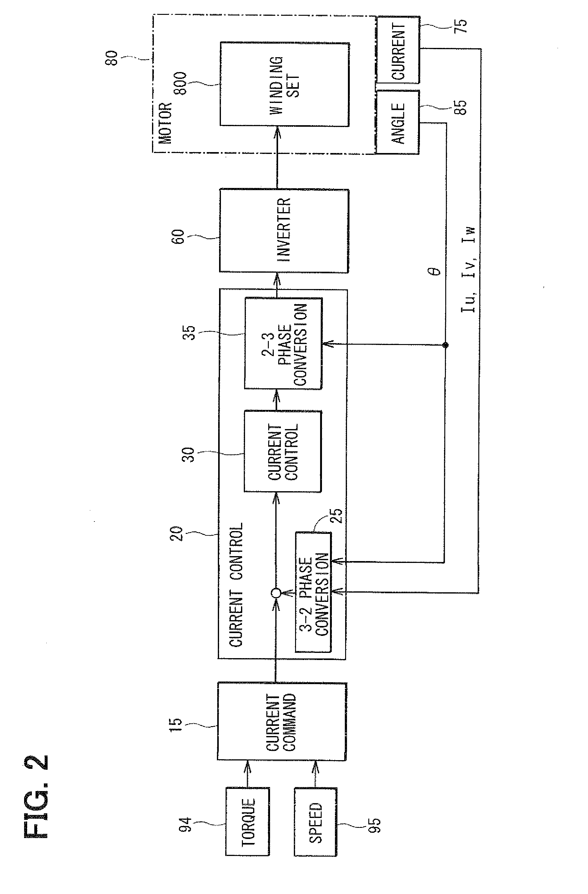
[0079]The function of each section is generally similar to that described with reference to the control block diagram of FIG. 2. The current command value calculation unit 15 outputs the d-axis current command value IDref and the q-axis current command value IQref. The current control calculation section 30 generates the repres...
PUM
 Abstract
Description
Claims
Application Information