Method and apparatus for controlling electric power steering system

a technology of electric power steering and electric motor, which is applied in the direction of damping of motor control for motor oscillation, non-deflectable wheel steering, underwater vessels, etc., can solve the problems of increasing cost and size, large torque ripple in the motor, and the failure of the motor to produce the necessary torqu

Active Publication Date: 2009-09-17
NSK LTD
View PDF12 Cites 67 Cited by
  • Summary
  • Abstract
  • Description
  • Claims
  • Application Information

AI Technical Summary

Benefits of technology

[0044]The foregoing objects of the present invention can be achieved more effectively by the current command value calculator that includes a first look-up table outputting a first limit value based on the value of the sum, a second look-up table outputting a base limit value based on the value of the sum, a first comparator comparing the steering assist current command value with the first limit value to output the limit value, a second comparator comparing the steering assist current command value with the base limit value to output a base command value, a third look-up table receiving the value of the sum and the limit value to output the d-axis current command value, a switch switchably outputting the limit value and the base limit value, and a sensing and switching unit detecting the magnitude of the value of the sum to switch the switch. Alternatively, the above-mentioned objects of the present invention can be achieved effectively either by a fit-change-to-battery-voltage unit that includes a fourth lookup table receiving the d-axis current command value and the limit value of the current command value to output a best-fit value, and a multiplier multiplying the battery voltage and the best-fit value, so that the multiplier outputs an amount of change in an angular speed, or by adopting a permanent magnet type brushless DC-motor as the motor.

Problems solved by technology

However, use of such a motor would involve a problem of increasing cost and size.
An abrupt turning-returning operation of the steering wheel that provides the vector control over a motor having such a current relationship as a condition will cause the motor to fail to produce the necessary torque.
The PWM-duty saturation results in a current waveform distortion, causing a large torque ripple in the motor, as a result of which, steering wheel vibration or abnormal motor noise is caused.
Such an attempt to perform the control beyond the limit of a rated torque output will result in the PWM-duty saturation and consequently a large torque ripple, causing the driver to experience steering wheel vibration or an unnatural steering feel.
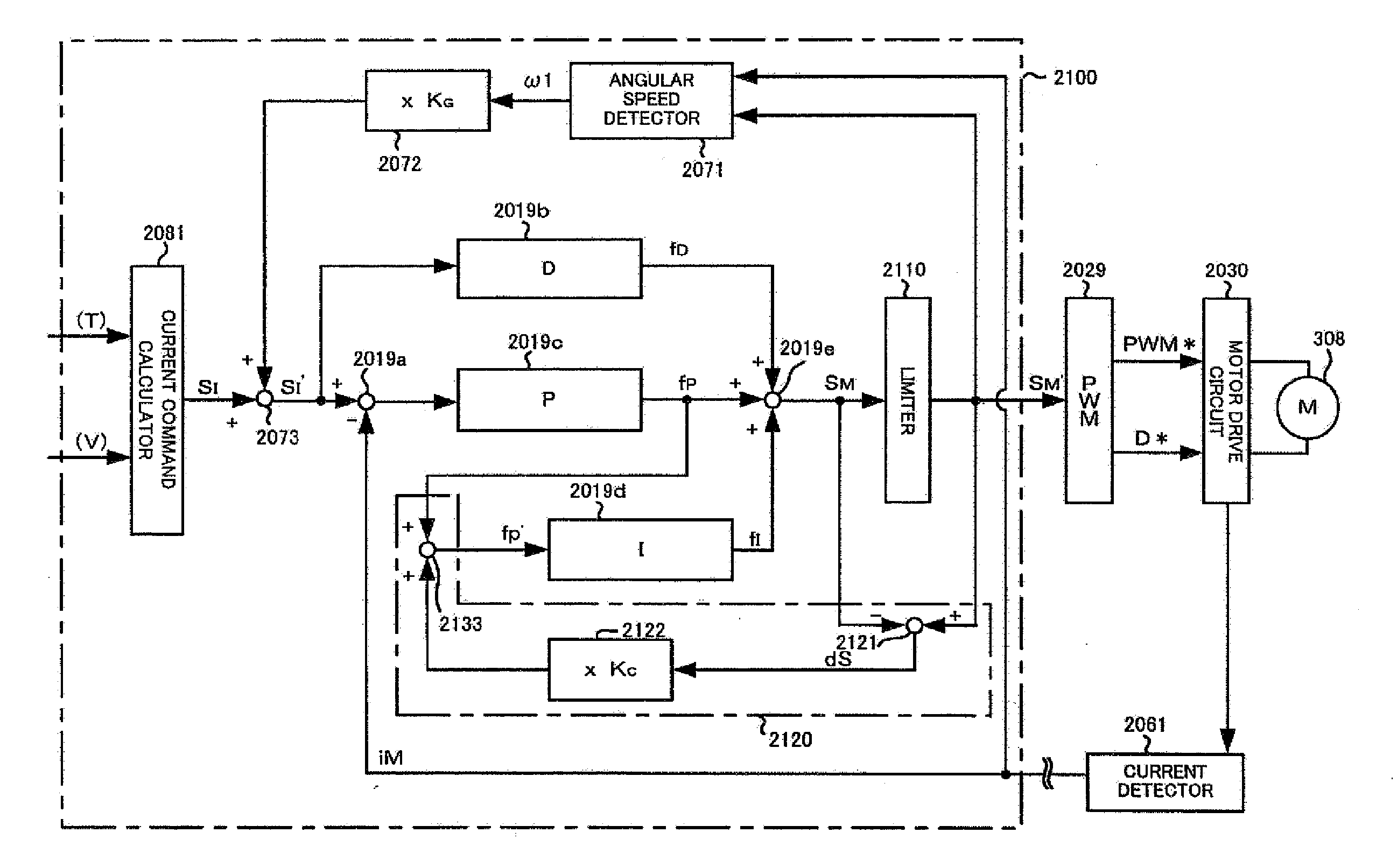
However, in the apparatus according to Japanese Patent Application Laid-open No. 08-142886 A, an output value to a PWM-circuit 2029 is limited by the limiter 2110, and hence the driver will still be left with an unnatural steering feel.
The first two concepts are relatively simple, but the constant power conditions cannot be maintained over a wide range of speed.
However, motor resistance is often ignored, resulting in significant calculation errors with, in particular, small motors.
When the steering wheel is turned back very quickly, a required steering assist torque will be too large for the motor to follow immediately.
Therefore, the motor cannot provide an accurate steering assist torque.
This means that a motor current limiting system such as the one described above (involving the limited motor power and the duty saturation) cannot provide a motor current corresponding to the current command value (reference current) directly proportional to the required torque.
In this condition, a torque ripple occurs resulting in an unnatural steering feel or abnormal noise.
This is because there is a problem of excessive noise caused by such factors as torque ripple due to overuse of the field-weakening control beyond the performance limits of the motor.

Method used


Image

  • Method and apparatus for controlling electric power steering system
  • Method and apparatus for controlling electric power steering system
  • Method and apparatus for controlling electric power steering system

Examples


case 2

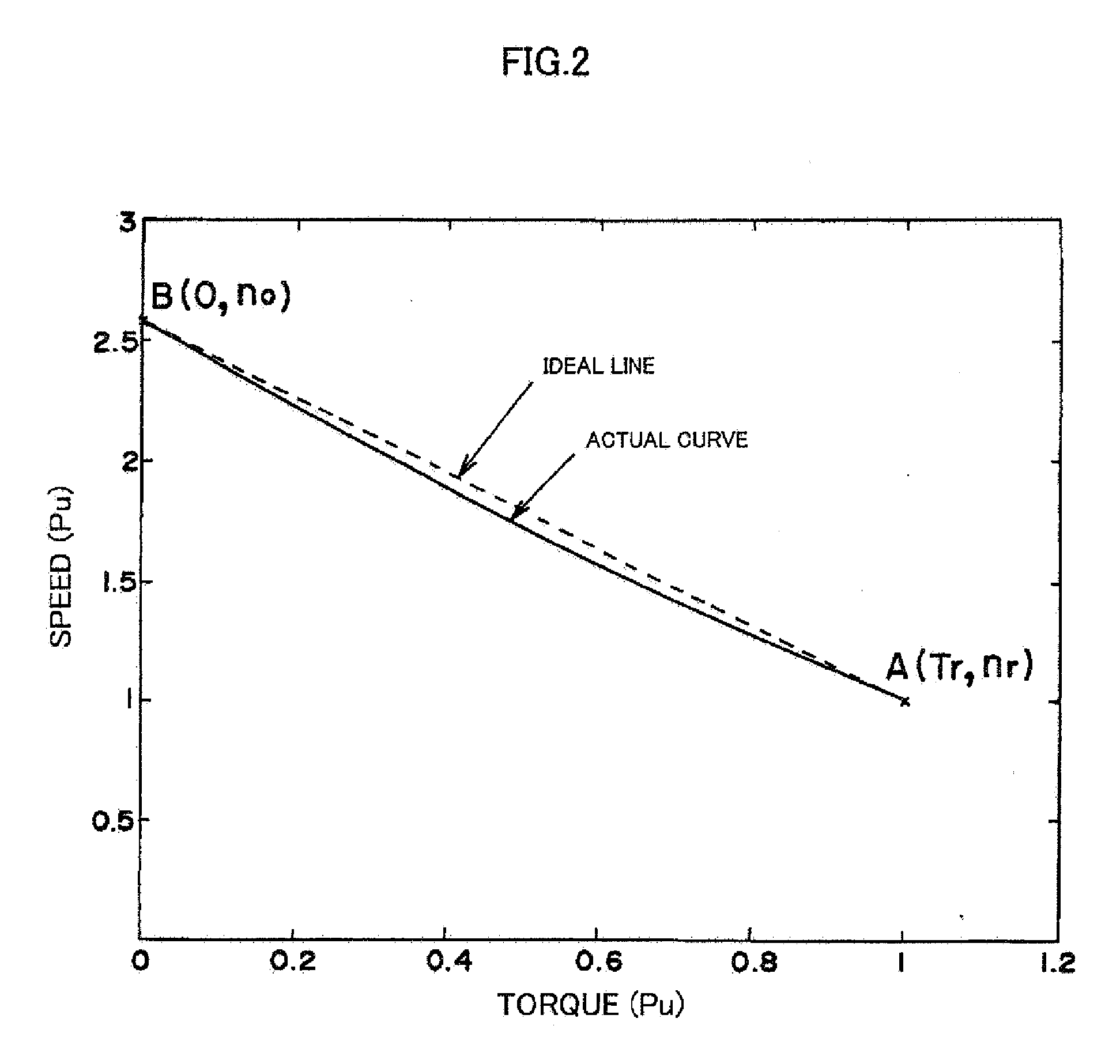
[0137 is a conventional technique for determining the d-axis current command value Id without having it exceed the maximum current in the above Formula 37. When the d-axis current is large, negative side effects such as reduced efficiency, vibration and noise occur. The field-weakening control is necessary to produce an output, but the d-axis current command value Id does not have to be a non-duty saturating maximum value. It is desirable that the d-axis current command value Id is a minimum value needed for producing the required output. A required output for an electric power steering system is a known design requirement and usually determined at the request of an automotive manufacturer (customer).

[0138]A point C in FIG. 13 represents a required output that cannot be produced without performing the field-weakening control. Therefore, the limit value of the d-axis current command value Id should be determined to yield the output represented by the point C. There is no need for pro...


PUM


Abstract

Disclosed herein is a method for controlling an electric power steering system, wherein a motor is controlled by vector control and driven by a current command value calculated on the basis of a parameter such as a steering torque to provide a steering assist power to a vehicle steering system, and further wherein the current command value is limited on the basis of desired output characteristics and a desired angular speed during a field-weakening control and a non-field-weakening control of the vector control.

Description

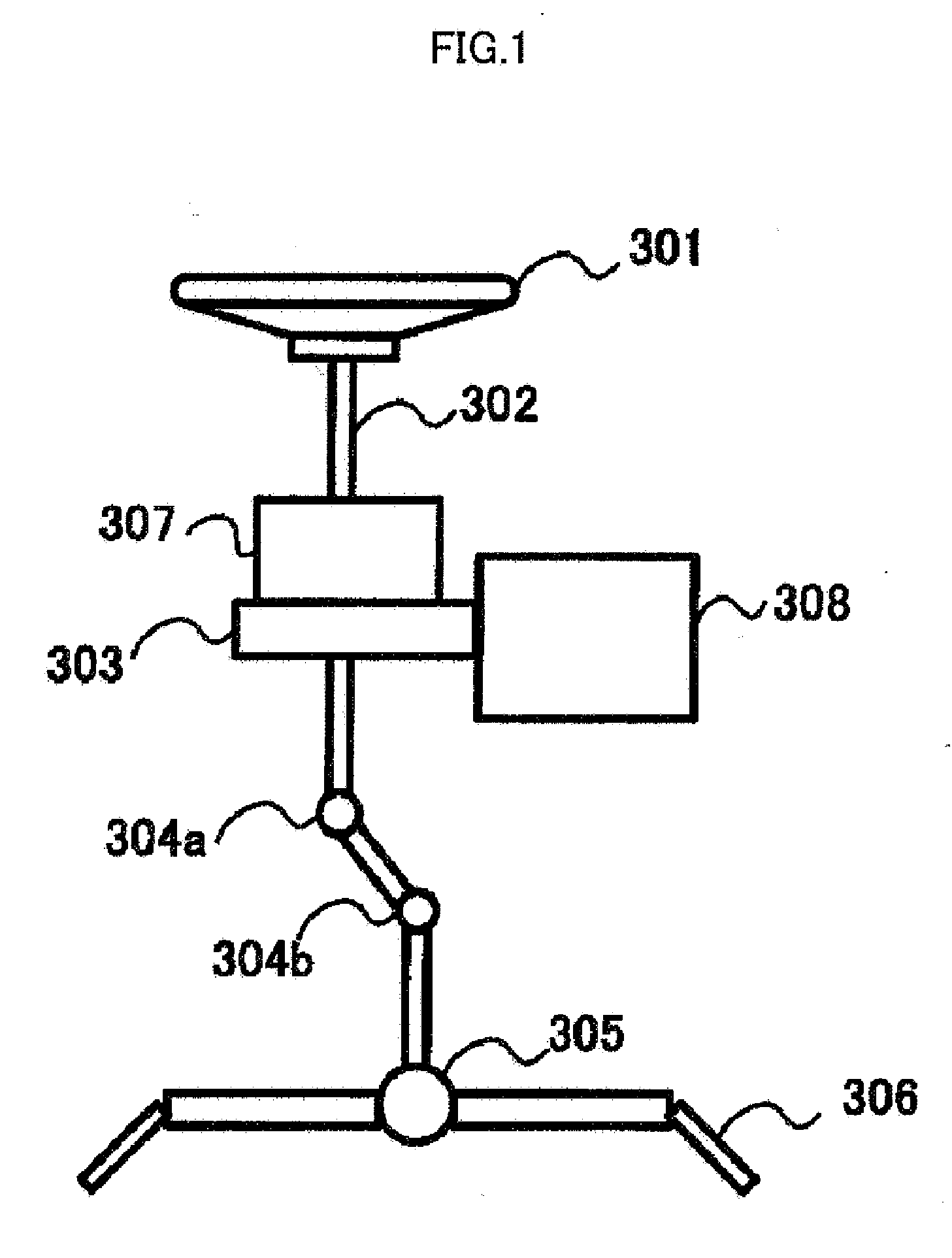
TECHNICAL FIELD[0001]The present invention relates to a method and apparatus for controlling an electric power steering system for use with a permanent magnet type brushless DC-motor, and in particular to a method and apparatus for controlling an electric power steering system in which a motor torque ripple which causes abnormal noise from a steering wheel during an abrupt steering wheel operation is reduced by limiting a current command value at a field-weakening control time of a d-axis current in a vector control and thereby setting a d-axis current as low as possible within a range meeting the requirement specifications.BACKGROUND ART[0002]Electric power steering apparatuses using motor torque to provide a power assist to steering are widely used in automobiles so as to allow a light steering operation. Such an electric power steering system includes a geared or belted transmission mechanism transmitting the driving force of a motor through a reducer to provide the power assist ...

Claims


Application Information

Patent Timeline
Patent Type & Authority Applications(United States)
IPC IPC(8): B62D5/04B62D6/00B62D119/00B62D137/00H02P6/06H02P6/08H02P6/17H02P6/28H02P21/00H02P21/05H02P21/22H02P23/04H02P23/24H02P27/04H02P27/08
CPCB62D5/046H02P21/04H02P21/0089B62D5/0463B62D5/00B62D5/04H02P21/02H02P27/04
Inventor TA, CAOMINHJIANG, CHUNHAOKOBAYASHI, HIDEYUKI
Owner NSK LTD
Why Eureka
Try Eureka