Control system and method for hybrid vehicle

a control system and hybrid technology, applied in the direction of electric propulsion mounting, electric devices, battery/cell propulsion, etc., can solve the problems of driver's inability to move the vehicle to a service station such as a repair shop, battery-less emergency traveling may be disabled, etc., to achieve the effect of effectively preventing steering assist for

Inactive Publication Date: 2010-01-14
TOYOTA JIDOSHA KK
View PDF10 Cites 73 Cited by
  • Summary
  • Abstract
  • Description
  • Claims
  • Application Information

AI Technical Summary

Benefits of technology

[0014]An object of the present invention is to provide a control system and a control method for a hybrid vehicle in which, even if during traveling of the hybrid vehicle with an electric power steering device, a defect arises in a battery of a high-voltage power source, battery-less emergency traveling can be achieved over a sufficiently long distance, and the steering assist force can be effectively prevented from changing rapidly during traveling.

Problems solved by technology

When a defect arises in the HV battery or the driving circuit, control processing is started when the defect is detected and is carried out after the system main relay has been turned off.
In this case, the vehicle may remain stopped on the road, and the battery-less emergency traveling may be disabled, and the driver cannot move the vehicle to a service station such as a repair shop.
This may make the driver feel discomfort.
However, the low-voltage battery has a small, limited capacity.
Thus, if the low-voltage battery is used to drive the electric power steering device, consumable energy is reduced, making continued use of the low-voltage battery difficult.

Method used


Image

  • Control system and method for hybrid vehicle
  • Control system and method for hybrid vehicle
  • Control system and method for hybrid vehicle

Examples


Embodiment Construction

[0036]An embodiment according to the present invention will be described below in detail with reference to the drawings. FIGS. 1 to 10 show an exemplary embodiment of the present invention.

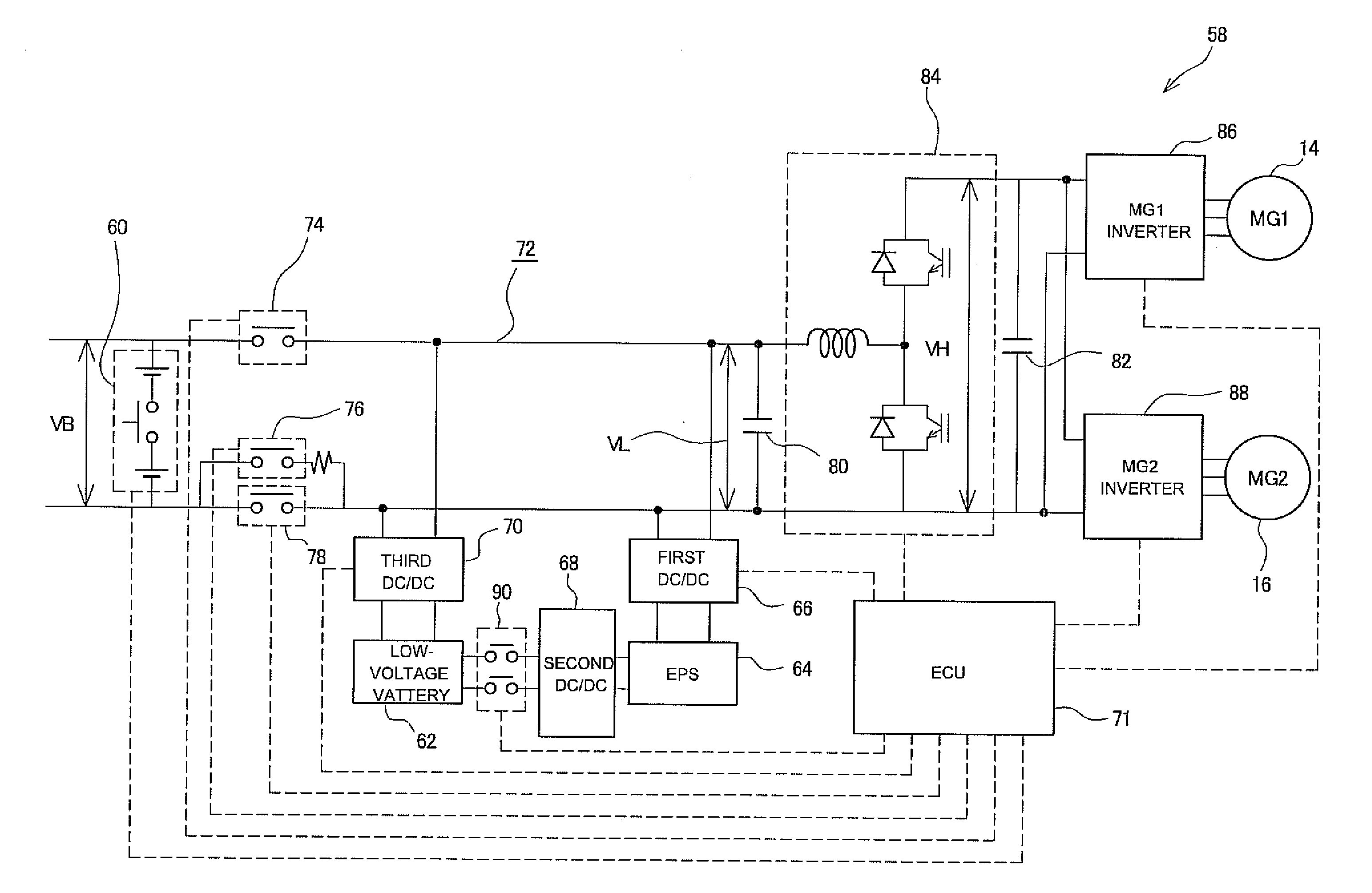
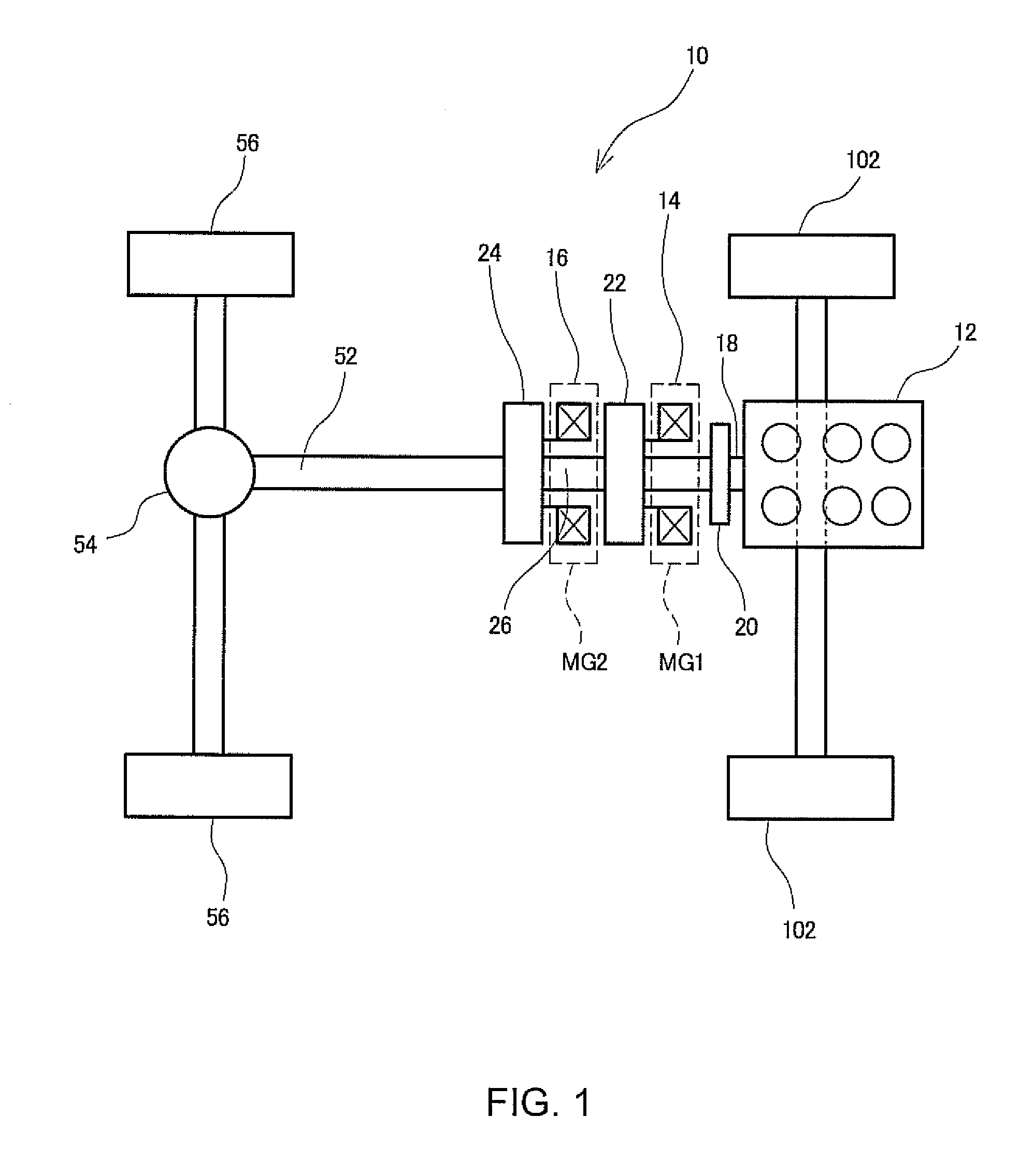
[0037]As shown in FIG. 1, a hybrid vehicle 10 is an FR vehicle that is a rear-wheel-drive vehicle with a front engine. The hybrid vehicle to be controlled according to the present invention is not limited to the FR vehicle but may be an FF vehicle that is a front-wheel-drive vehicle with a front engine or a 4WD vehicle that is a four-wheel-drive vehicle. The hybrid vehicle 10 includes an engine 12, a generator (MG1) 14 that is a first motor generator, and a traveling motor (MG2) 16 that is a second motor generator. The hybrid vehicle 10 is driven to travel using at least one of the engine 12 and the traveling motor 16 as a main driving source.

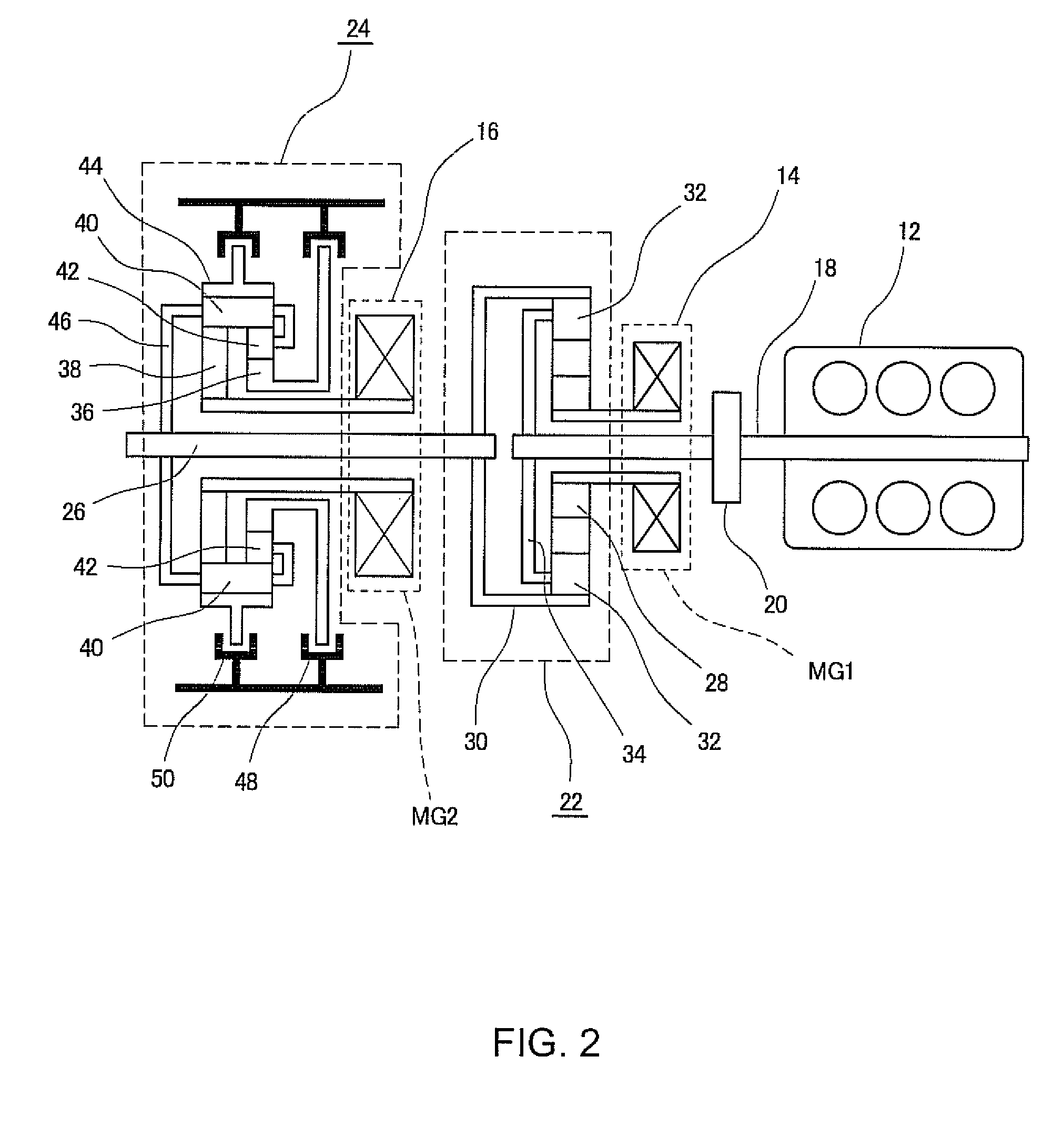
[0038]For such traveling driving, in the hybrid vehicle 10, a power-dividing section 22 is coupled to a crank shaft 18 of the engine 12 via a damper 20. A ro...


PUM


Abstract

The present invention is to provide a control system for a hybrid vehicle in which, even if during traveling of the hybrid vehicle, a battery defect arises in a high-voltage power source, battery-less emergency traveling can be achieved over a sufficiently long distance, and the steering assist force can be effectively prevented from changing rapidly during traveling. The control section includes high-voltage power source defect processing unit. During execution of a mode in which the high-voltage power source, is reduced so that the reduced voltage is supplied to an electric power steering device (EPS), when a defect occurs in the high-voltage power source, the high-voltage power source defect processing unit shifts to a mode in which the low voltage of a low-voltage power source is increased so that the increased voltage is supplied to the EPS. The high-voltage power source defect processing unit then disconnects the high-voltage power source and the driving circuit from each other. Thereafter, the control section shifts to a mode in which a voltage corresponding to power generated by a generator is reduced so that the reduced voltage is supplied to the EPS, while allowing the generator to drive a traveling motor.

Description

PRIORITY INFORMATION[0001]This application claims priority to Japanese Patent Application No. 2008-181304 filed on Jul. 11, 2008, which is incorporated herein by reference in its entirety.BACKGROUND[0002]The present invention relates to a control system and a control method for a hybrid vehicle driven to travel by unit of at least one of an engine and a traveling motor and including a generator driven by the engine, a high-voltage power source connected to the generator and the traveling motor via a driving circuit, a low-voltage power source charged at a voltage lower than that of the high-voltage power source, and an electric power steering device connected to the driving circuit via a voltage-reducing circuit and driven by supplied power of a voltage intermediate between the low voltage of the low-voltage power source and the high voltage of the high-voltage power source.RELATED ART [0003]Hybrid vehicles driven to travel by unit of at least one of an engine and a traveling motor ...

Claims


Application Information

Patent Timeline
Patent Type & Authority Applications(United States)
IPC IPC(8): B60W10/08B60W20/00B60L50/16
CPCB60K1/02Y02T10/7241B60K6/365B60K6/445B60K6/52B60K6/547B60L3/0046B60L11/123B60L11/14B60L2210/40B60L2240/421B60L2240/423B60L2270/20B60W10/06B60W10/08B60W10/30B60W20/00B60W50/04B60W2510/081B60W2710/083B62D5/046B62D5/0481B62D5/0484Y02T10/6217Y02T10/6239Y02T10/6265Y02T10/6286Y02T10/642Y02T10/7005Y02T10/7077B60K6/34B60L50/61B60L50/16Y02T10/62Y02T10/64Y02T10/72Y02T10/7072Y02T10/70B60W50/02
Inventor KISHIMOTO, TAKESHI
Owner TOYOTA JIDOSHA KK
Why Eureka
Try Eureka