
Intravenous catheter introducing device

a catheter and intravenous technology, applied in the field of intravenous catheter introduction devices, can solve the problems of prolonging the cannulation procedure, causing patients to be uncomfortable, and causing patients to be irritated, so as to prevent the blood from being forced out of the catheter and operate easily and safely.

Inactive Publication Date: 2010-08-10
SHUE MING JENG +2
View PDF34 Cites 40 Cited by
  • Summary
  • Abstract
  • Description
  • Claims
  • Application Information

AI Technical Summary

Benefits of technology

"The present invention provides an intravenous catheter introducing device that can be easily and safely operated with one hand to retract a used needle cannula. The device includes a needle cannula, a tubular needle seat, a barrel, a tubular grip member, a tubular plunger, a tubular receptacle, a biasing member, a catheter hub, and a tubular catheter. The device can facilitate flowing of blood into the needle cannula to allow for convenient and safe observation of the catheter introduction process. The device is designed to prevent blood from being forced out of the needle cannula and to provide a convenient and safe way to retract the needle cannula."

Problems solved by technology

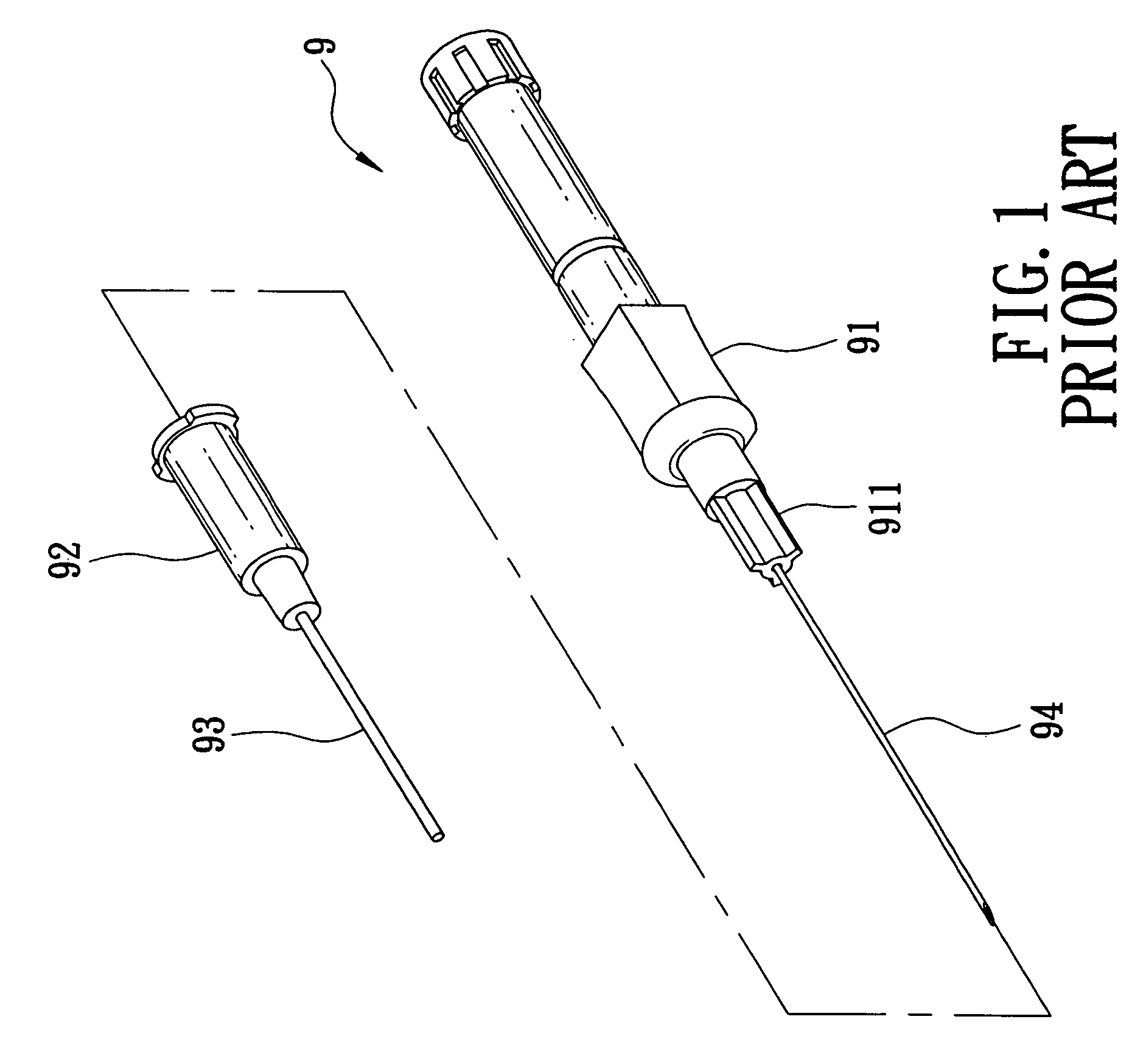
At this time, the exposed sharp tip of the used needle cannula 94 may create a danger of an accidental needle stick.
Moreover, the conventional intravenous catheter introducing device 9 is specifically not suitable for patients whose blood pressure is not sufficient to permit flow of blood therethrough, such as an emergency case, aged people, and pediatrics patients, and patients whose target vein is barely visible due to abundant adipose tissue, such as women and obese patients, since the health care worker will have difficulty determining whether the catheter 93 has been successfully introduced into the target vein, and may need to locate the vein by moving the needle cannula 94 in the skin of the patient, thereby complicating and prolonging the cannulation procedure and causing great discomfort to the patient.
Furthermore, although conventional self-retracting IV catheter introducers permit self-retraction of the used needle cannula into the syringe barrel after introduction of the catheter is completed, the blood in the barrel may be forced out of the barrel during the retraction of the used needle cannula so that blood contamination may occur.

Method used


Image

  • Intravenous catheter introducing device
  • Intravenous catheter introducing device
  • Intravenous catheter introducing device

Examples


Embodiment Construction

[0037]Before the present invention is described in greater detail, it should be noted that same reference numerals have been used to denote like elements throughout the specification.

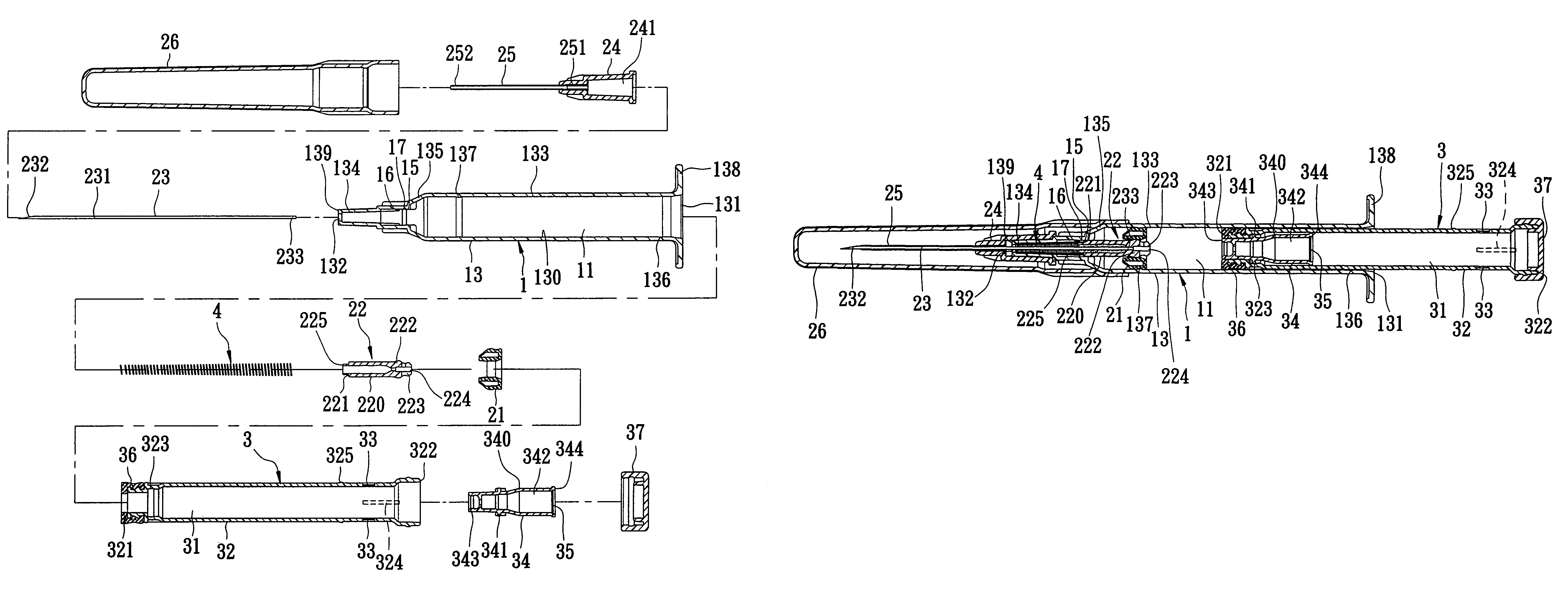
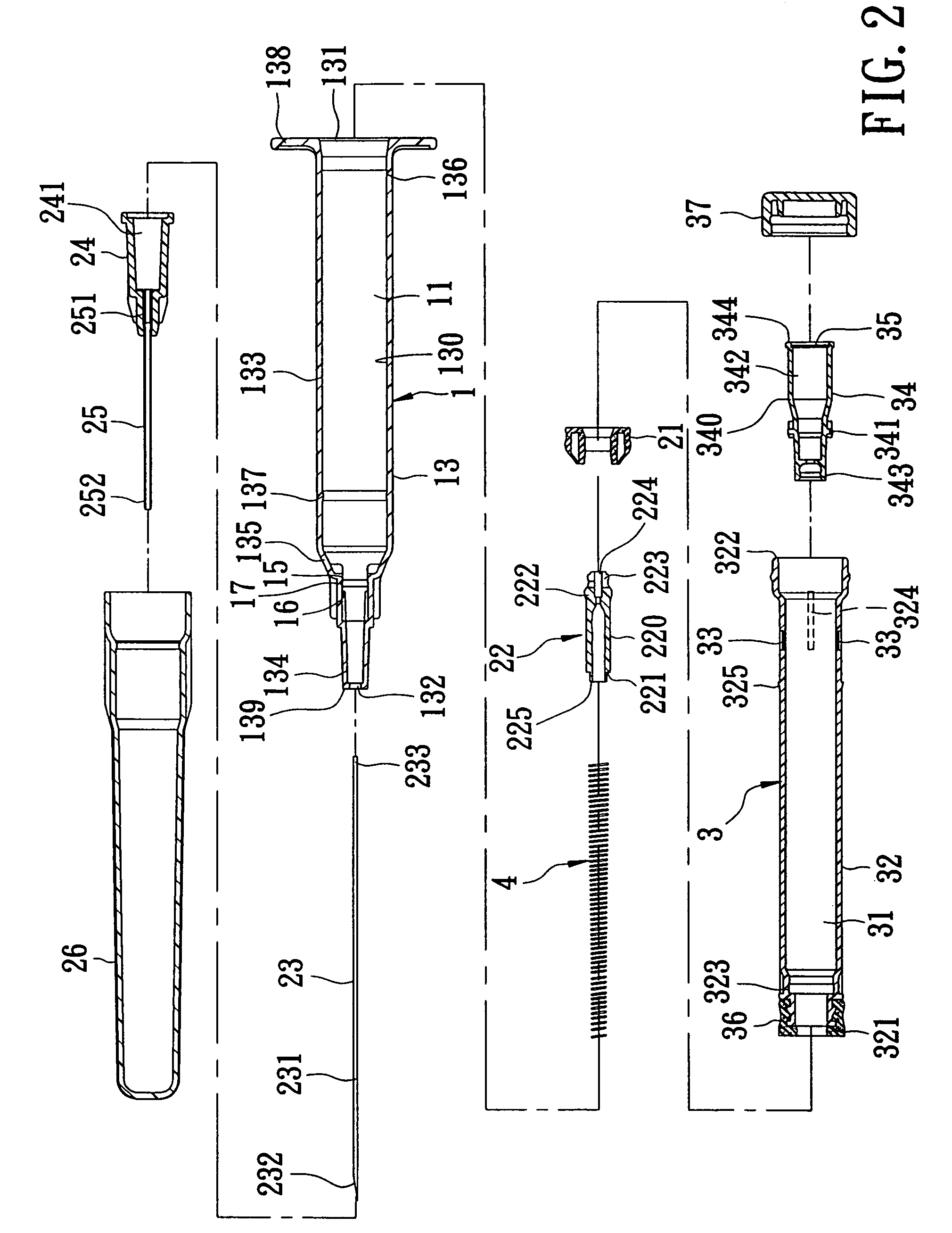
[0038]Referring to FIGS. 2 to 4, the first preferred embodiment of an intravenous catheter introducing device according to the present invention is shown to comprise a barrel 1, a needle cannula 23, a tubular needle seat 22, a tubular grip member 21, a tubular plunger 3, a tubular receptacle 34, a biasing member 4, a catheter hub 24, a tubular catheter 25, and a tip protector 26.

[0039]The barrel 1 has a surrounding wall 13 surrounding an axis. The surrounding wall 13 has an inner surrounding barrel surface 130 which defines a passage 11 therein. The passage 11 has rearward and forward openings 131,132 which are opposite to each other in a longitudinal direction along the axis. The inner surrounding barrel surface 130 includes a larger-diameter portion 133 and a smaller-diameter portion 134 which are dis...


PUM


Abstract

An intravenous catheter introducing device includes a barrel, a tubular grip member disposed to hold a needle seat in a position of use so as to permit a tip end of a needle cannula to extend forwardly of the barrel, a tubular plunger which is movable along a passage of the barrel, and a tubular receptacle which is retained in an accommodation compartment of the tubular plunger and which has socket and air-permeable ends and a flashback chamber. When the plunger is pressed forwardly to permit engagement of the socket end with a rear plug portion of the needle seat and to release the grip member from the barrel, a rearward movement of the needle seat by virtue of a biasing force of a biasing member will force the receptacle to move rearwardly so as to retract the needle cannula into the passage.

Description

CROSS-REFERENCE TO RELATED APPLICATION[0001]This application claims priority of Taiwanese Application No. 095121678, filed on Jun. 16, 2006, the disclosure of which is incorporated herein by reference.BACKGROUND OF THE INVENTION[0002]1. Field of the Invention[0003]This invention relates to an intravenous catheter introducing device, more particularly to an intravenous catheter introducing device with a needle cannula which is retractable into a tubular plunger for safe disposal.[0004]2. Description of the Related Art[0005]Intravenous catheter introducing devices are generally used to administer a medication fluid into or to draw blood from a patient's vein. Referring to FIG. 1, a conventional intravenous catheter introducing device 9 is shown to include a tubular needle seat 91 with a hub end 911, a needle cannula 94 secured to the hub end 911, a catheter hub 92 sleeved on the needle seat 91, and a flexible tubular catheter 93 secured to the catheter hub 92. In use, the catheter 93 ...

Claims


Application Information

Patent Timeline
Patent Type & Authority Patents(United States)
IPC IPC(8): A61M5/178
CPCA61M25/0606A61M25/0631A61M25/0693
Inventor SHUE, MING-JENGSHUE, PHILLIPHUANG, DEBORAH
Owner SHUE MING JENG
Learn More