Cable support structure

Active Publication Date: 2006-02-14
HONDA MOTOR CO LTD
View PDF10 Cites 34 Cited by
  • Summary
  • Abstract
  • Description
  • Claims
  • Application Information

AI Technical Summary

Benefits of technology

[0011]Accordingly, even in the case where the attitude angle of the first member or the second member with respect to the vertical direction changes in correspondence to the movement or the vertical position changes, it is possible to prevent an unreasonable force from being applied to the cable guide on the basis of the change in attitude or position, so that it is possible to correspond to the change in attitude angle and the change in position of the first member or the second member with respect to the vertical direction.
[0012]Further, in the case of the structure that both the first support member and the second suppo

Problems solved by technology

However, in the conventional structure, there is a problem in that the electric current can be fed to the slide door at

Method used


Image

  • Cable support structure
  • Cable support structure
  • Cable support structure

Examples


Embodiment Construction

[0033]Hereinafter, description will be given of a cable support structure according to an embodiment of the present invention. In the present embodiment, the description is given of an embodiment in which a cable support structure is applied to a vehicle main body and a slide door; however, a subject to be applied is not limited thereto. The present cable support structure can be applied to a first member and a second member which relatively move along a predetermined moving direction.

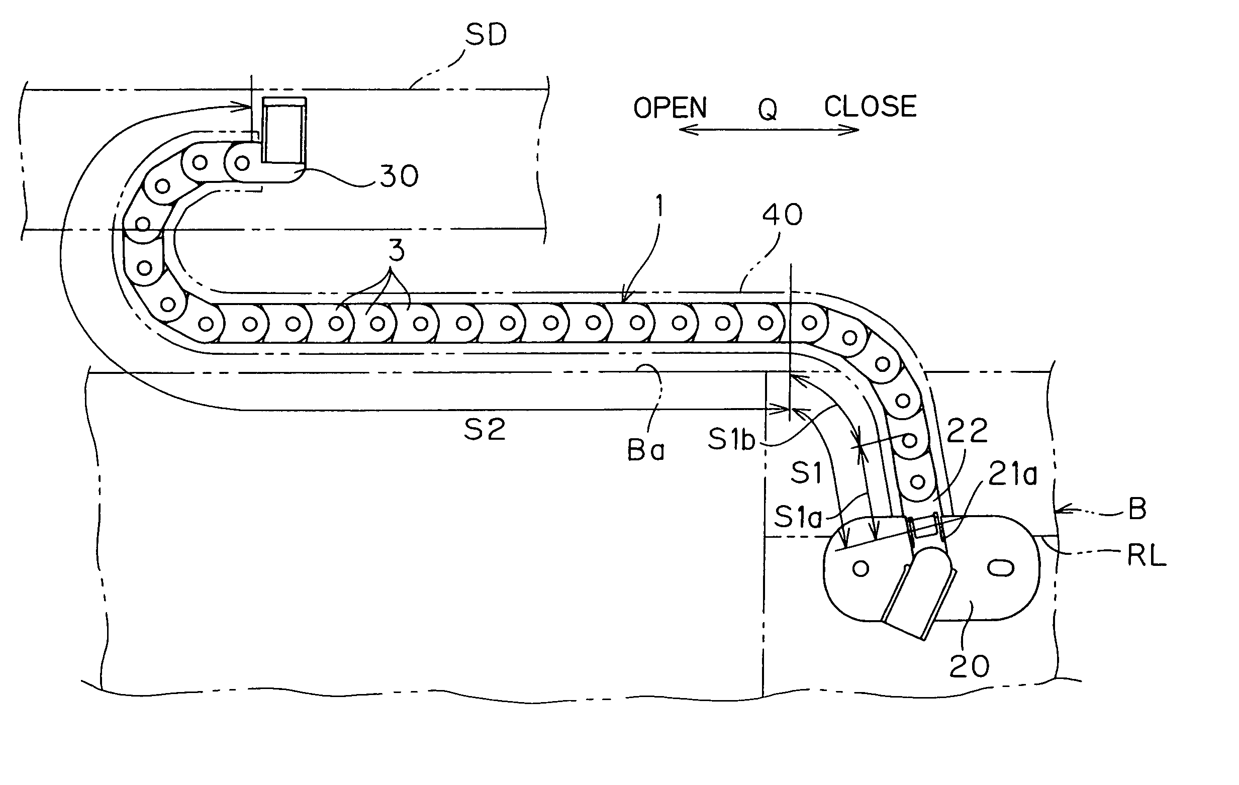
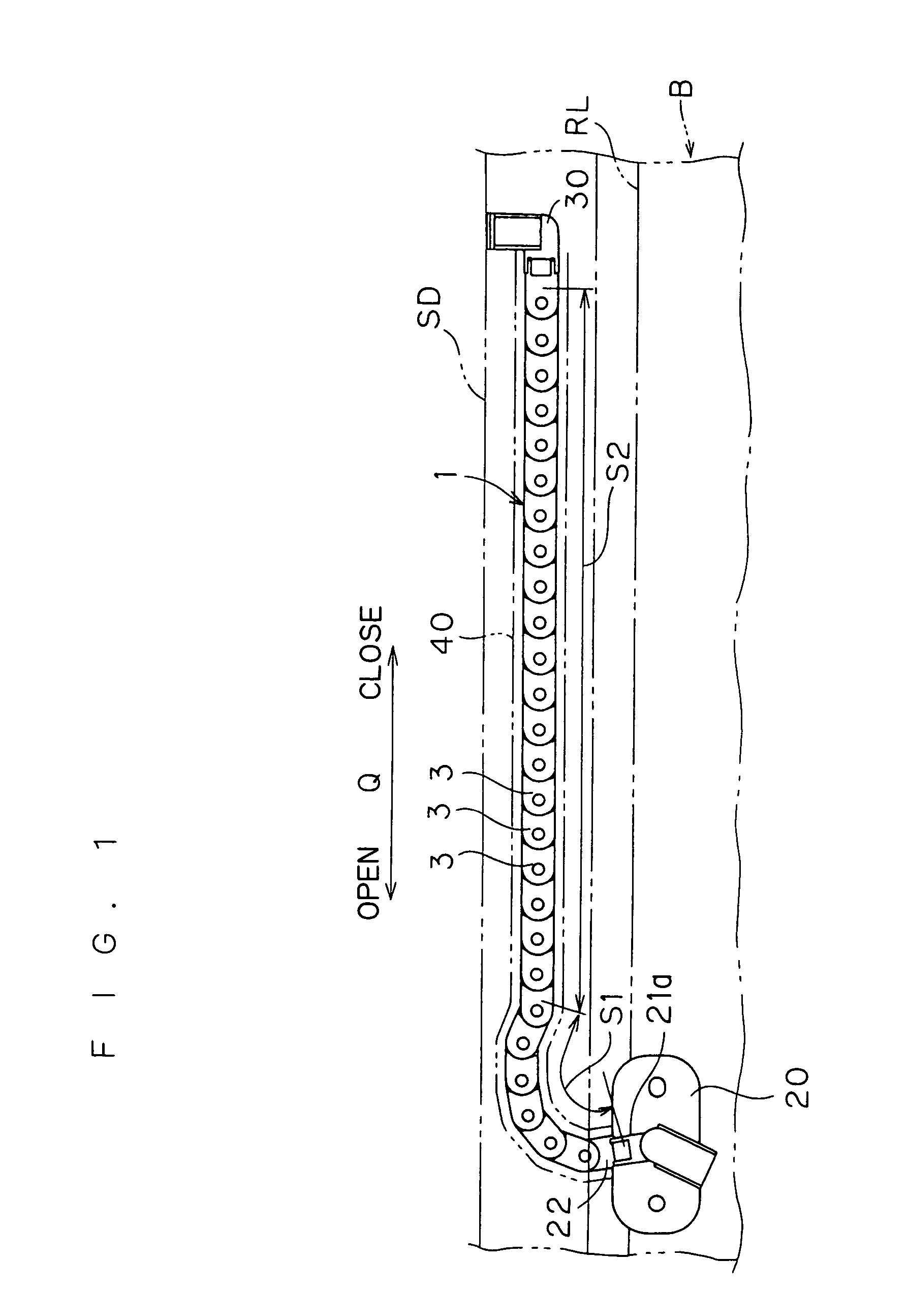
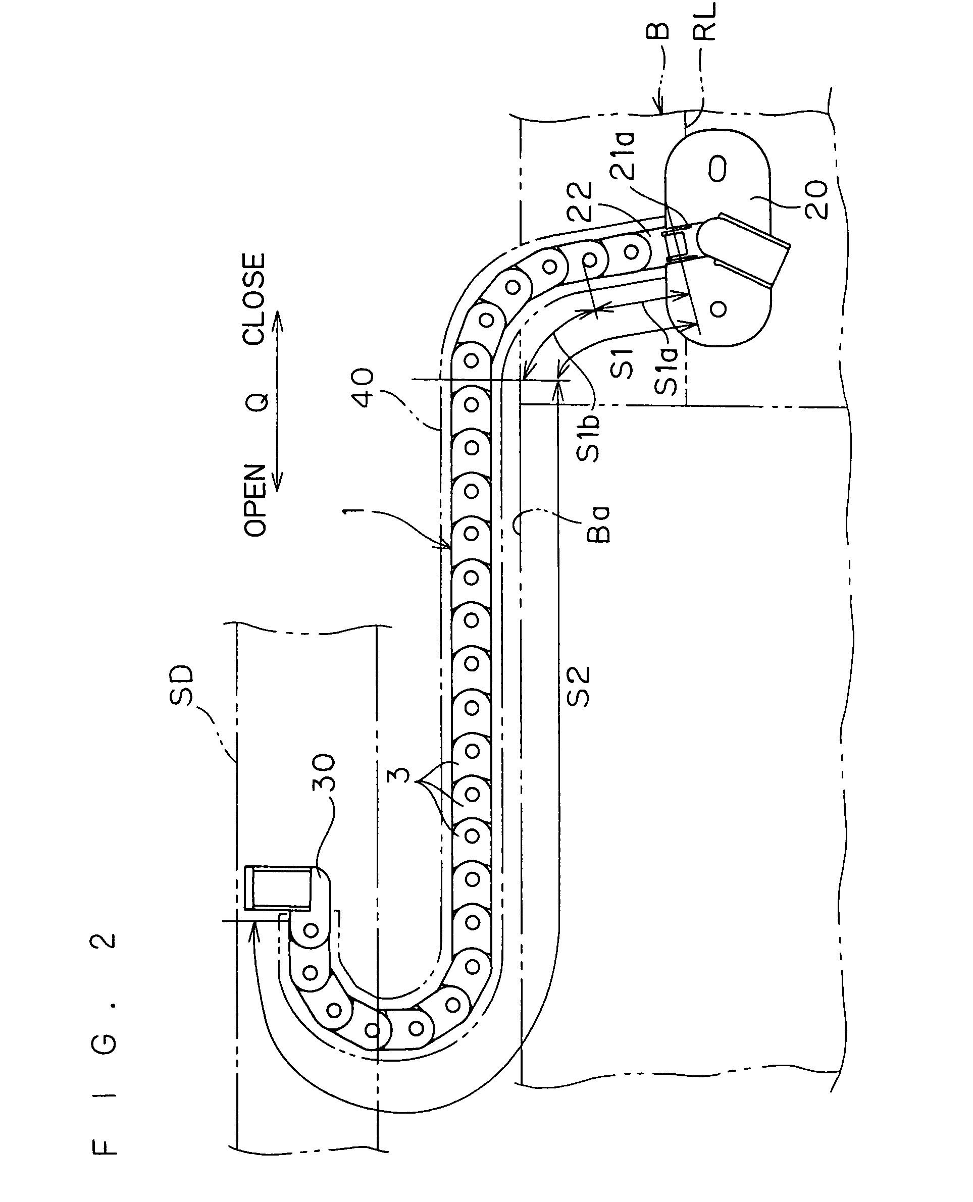
[0034]FIG. 1 is a schematic plan view of the cable support structure in a state where a slide door SD is closed, FIG. 2 is a schematic plan view of the cable support structure in a state where the slide door SD is opened, and FIG. 3 is a view showing a state when the slide door SD is opened and closed.

[0035]This cable support structure is structured such as to guide bending of a cable 2 (shown only in FIG. 15) arranged between a vehicle main body B and a slide door SD, as shown in FIGS. 1 to 3, and is ...


PUM

PropertyMeasurementUnit
Forceaaaaaaaaaa
Angleaaaaaaaaaa

Abstract

When a cable support structure according to the present invention is applied to a slide door in a vehicle, a first support member (20) and a second support member (30) support one end portion and another end portion in a cable guide (1) in a state capable of swinging them in a vertical direction approximately perpendicular to a sliding direction (Q) of a slide door (SD). Accordingly, even in the case where an attitude angle of the slide door (SD) with respect to the vertical direction is changed in correspondence to the slide movement, or a vertical position is changed, it is possible to prevent an unreasonable force from being applied to the cable guide (1) on the basis of the above-described attitude or position change.

Description

BACKGROUND OF THE INVENTION[0001]1. Field of the Invention[0002]The present invention relates to a cable support structure for supporting a cable which is arranged between relatively moving two members.[0003]2. Description of the Background Art[0004]Conventionally, there is, for example, a structure that impinging type terminals are provided on a slide door side of a vehicle and a vehicle main body side and, when the slide door is closed, the terminal in the door side and the terminal in the vehicle main body side are impinged so as to be electrically connected, whereby an electric current is fed from the vehicle main body side to the door side via both the terminals.[0005]However, in the conventional structure, there is a problem in that the electric current can be fed to the slide door at the time when the slide door is closed, but the electric current can not be fed in a state where the slide door is open.[0006]Accordingly, there is proposed a structure that a cable is arranged b...

Claims


Application Information

Patent Timeline
IPC IPC(8): F16G13/00B60J5/06B60R16/02E05F15/14F16G13/16H02G3/04H02G3/38H02G11/00H05K7/00
CPCB60R16/0215F16G13/16E05F15/646E05Y2400/654E05Y2900/531E05Y2800/344Y10S59/90
Inventor KOBAYASHI, YOSHINAO
Owner HONDA MOTOR CO LTD
Why Eureka
Try Eureka