Method and system for topology construction and path identification in a two-level routing domain operated according to a simple link state routing protocol

a topology and routing domain technology, applied in the field of topology construction and path identification in a two-level routing domain operated according to a simple link state routing protocol, can solve the problems of difficult for a network administrator to have a global view of the network at any given time, many of the network management functions available for networks based on more traditional technologies, e.g., connection-oriented frame relay or asynchronous transfer mode (atm), and difficult for a network administrator to precisely identify. to achiev

Active Publication Date: 2006-10-10
SONS OF INNOVATION LLC
View PDF24 Cites 53 Cited by
  • Summary
  • Abstract
  • Description
  • Claims
  • Application Information

AI Technical Summary

Benefits of technology

[0013]In accordance with one embodiment of the present invention, a method for constructing topology and routing information in a two level multi-area routing domain that includes a plurality of level one areas and a level two area and which is operated according to a simple link state routing protocol, includes the steps of (i) acquiring topology and routing information, including route entries, for each area in the routing domain; (ii) within each level one area, identifying possible level one exit points into the level two area; (iii) for each level one exit point through which a route entry known in the level one area can be reached, determining a cost of reaching the route entry from the level one exit point; (iv) for each route entry known in the level two area, identifying at least one level two exit point out of the level two area; (v) for each level two exit point through which a route entry can be reached, determining a cost of reaching the route entry from the level two exit point; and (vi) for all exit points out of the level two area, determining the set of level one areas, if any, to which they connect.
[0014]In accordance with an alternate embodiment, a method for constructing end-to-end paths between a specified origin and a specified destination in a two-level multi-area routing domain operated according to a simple link state routing protocol includes the steps of: (i) acquiring topology and routing information for each area in the routing domain; (ii) identifying an origin area and an entry point in the origin area; (iii) determining whether the origin area is a level one area or level two area; (iv) retrieving a route entry in the origin area, where the route entry is associated with a specified destination; (v) extracting a set of exit points from the origin area through which the route entry associated with the specified destination can be reached; and (vi) computing shortest paths in the origin area between the entry point and each exit point in

Problems solved by technology

However, the distributed mode of operation of routing protocols such as IS-IS makes it difficult for a network administrator to have a global view of the network at any given time.
Because of this, many of the network management functions that are available for networks based on more traditional technologies, e.g., connection-oriented such frame relay or asynchronous transfer mode (ATM), are difficult if not impossible to replicate in IP networks.
This makes it difficult for a network administrator to precisely identify the path that the traffic between, for example, two customer sites, is following when traversing the network.
As a consequence, upon identifying a highly congested link, a network administrator has no or only limited visibility into which customers may be experiencing poor performance as a result of this congestion.
Similarly, in the presence of a link failure, identifying which customers are immediately affected as well as predicting which ones may also experience a change in service performance shortly after the failure is again a very complex task in IP networks.
Manage

Method used


Image

  • Method and system for topology construction and path identification in a two-level routing domain operated according to a simple link state routing protocol
  • Method and system for topology construction and path identification in a two-level routing domain operated according to a simple link state routing protocol
  • Method and system for topology construction and path identification in a two-level routing domain operated according to a simple link state routing protocol

Examples


Embodiment Construction

[0034]A preferred embodiment of the present invention provides an improved method and system for monitoring, tracking, and / or predicting the routing path of one or more packets under a simple IP routing protocol such as the IS-IS protocol.

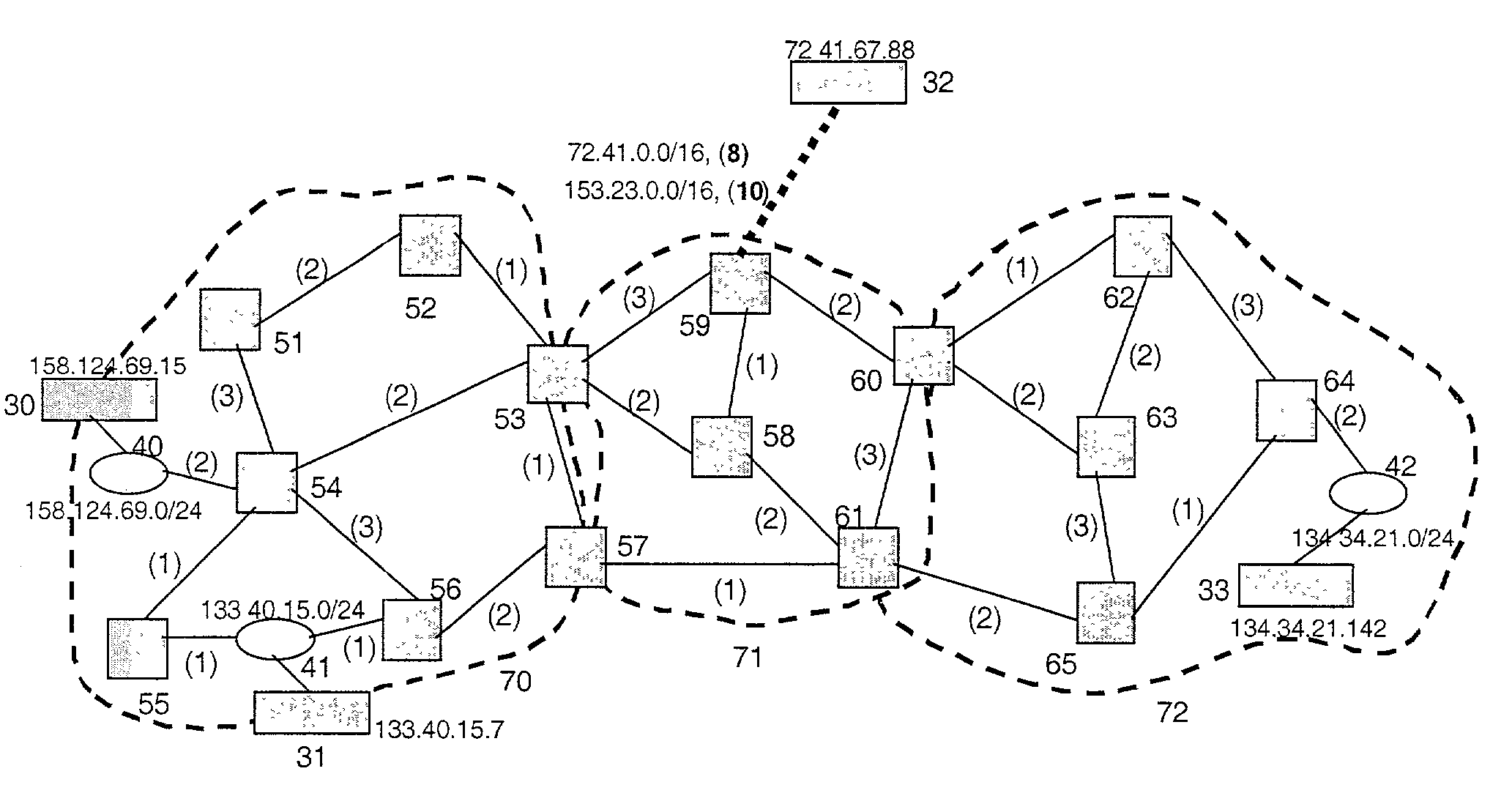
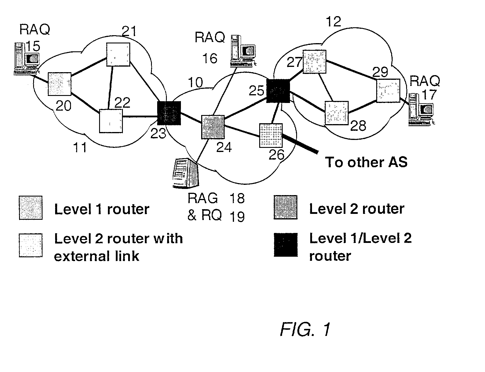
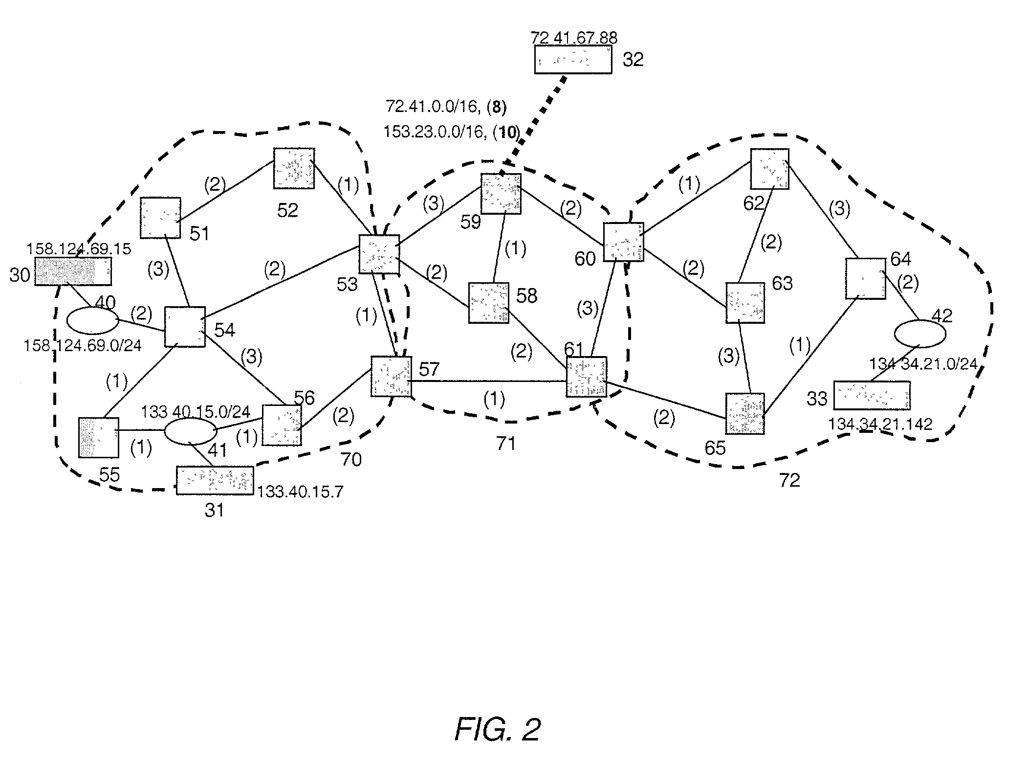
[0035]The present invention allows a network administrator, network monitoring system, or other human or automated user to identify the path or paths followed or expected to be followed by any packet traveling though a two-level, multi-area routing domain or AS, where the packet has a known entry point or address and a known or anticipated destination address. The destination address is associated with a routing entry, typically from a routing table, and the present invention constructs the path that was or is expected to be followed through the routing domain by the packet associated with the routing entry. Optionally and preferably, when more than one path is possible, the invention is capable of constructing the complete set of possible paths, a...


PUM


Abstract

A method and system for extracting and building end-to-end route information in a two-level, multi-area Internet protocol (IP) autonomous system (AS) operated according to a simple link state routing protocol such as the Integrated System to Integrated System (IS-IS) protocol is disclosed. The method and system enables a user, such as a network administrator, to explicitly identify a full set of paths (links and routers) that a given IP packet would potentially traverse from its entry point in the area of the AS where it originates until its exit point in its intended destination or exit area.

Description

RELATED APPLICATIONS[0001]This application claims priority to, and is a continuation-in-part application of, U.S. patent application Ser. No. 09 / 997,420, filed Nov. 29, 2001, now U.S. Pat. No. 6,836,465, which is incorporated herein by reference in its entirety.FIELD OF THE INVENTION[0002]The present invention relates generally to a method and system for acquiring information from an Internet Protocol (IP) two-level, multi-area routing domain operating according to a simple link state routing protocol such as the Intermediate System to Intermediate System (IS-IS) routing protocol. More particularly, the present invention relates to a method and system for determining the set of links and routers that are traversed by traffic to and / or from an individual user in a communications network where routing is determined according to a simple link state routing protocol, such as the IS-IS protocol.BACKGROUND OF THE INVENTION[0003]An Internet protocol (IP) network is a large distributed syst...

Claims


Application Information

Patent Timeline
IPC IPC(8): H04L12/26G06F15/173H04L12/28H04J1/16H04L12/24H04L12/715H04L12/721H04N7/26H04N11/04
CPCH04L41/12H04L45/02H04L45/04H04L45/12H04L45/123H04L45/26H04N11/042H04N19/186H04N19/184H04L45/124H04L45/03
Inventor GUERIN, ROCHRAJAN, RAJENDRAN
Owner SONS OF INNOVATION LLC
Why Eureka
Try Eureka