Breaker for protecting electric facilities

a technology for protecting electric facilities and electric facilities, which is applied in the direction of circuit-breaking switches, dynamo-electric relays, relays, etc., can solve the problems of easy damage to electric facilities and large voltage generated within electric facilities

Inactive Publication Date: 2006-11-07
CHUNG RONG LIN G +1
View PDF6 Cites 10 Cited by
  • Summary
  • Abstract
  • Description
  • Claims
  • Application Information

AI Technical Summary

Problems solved by technology

However, when the electric power is supplied to the electric facilities again, a great voltage may be generated within the electric facilities, such that the electric facilities may be easily damaged after the termination of the electric power and when the electric power is supplied to the electric facilities again.

Method used


Image

  • Breaker for protecting electric facilities
  • Breaker for protecting electric facilities
  • Breaker for protecting electric facilities

Examples


Embodiment Construction

[0016]In order that those skilled in the art can further understand the present invention, a description will be described in the following in details. However, these descriptions and the appended drawings are only used to cause those skilled in the art to understand the objects, features, and characteristics of the present invention, but not to be used to confine the scope and spirit of the present invention defined in the appended claims.

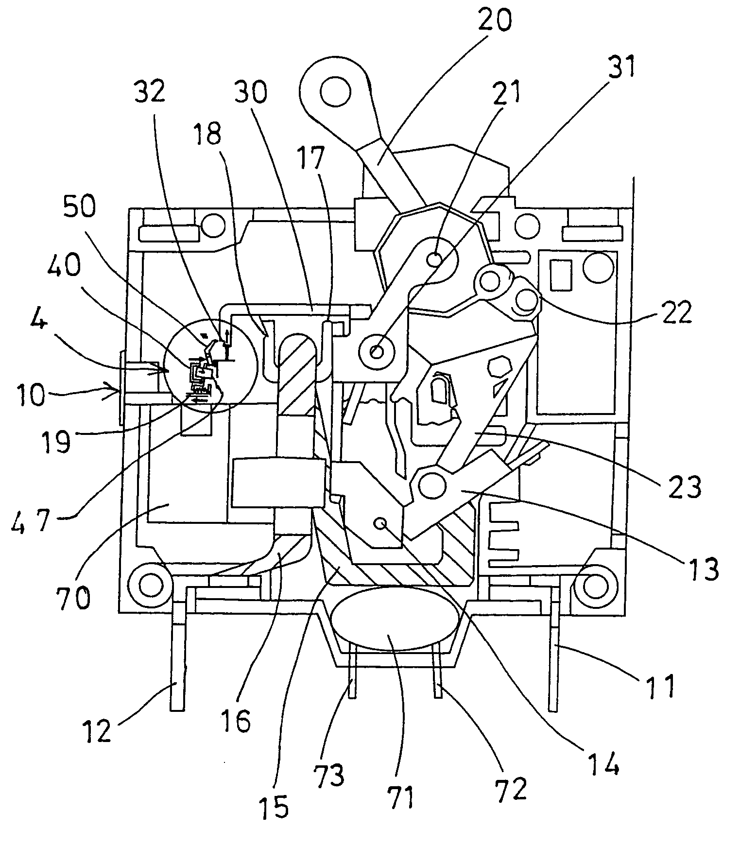
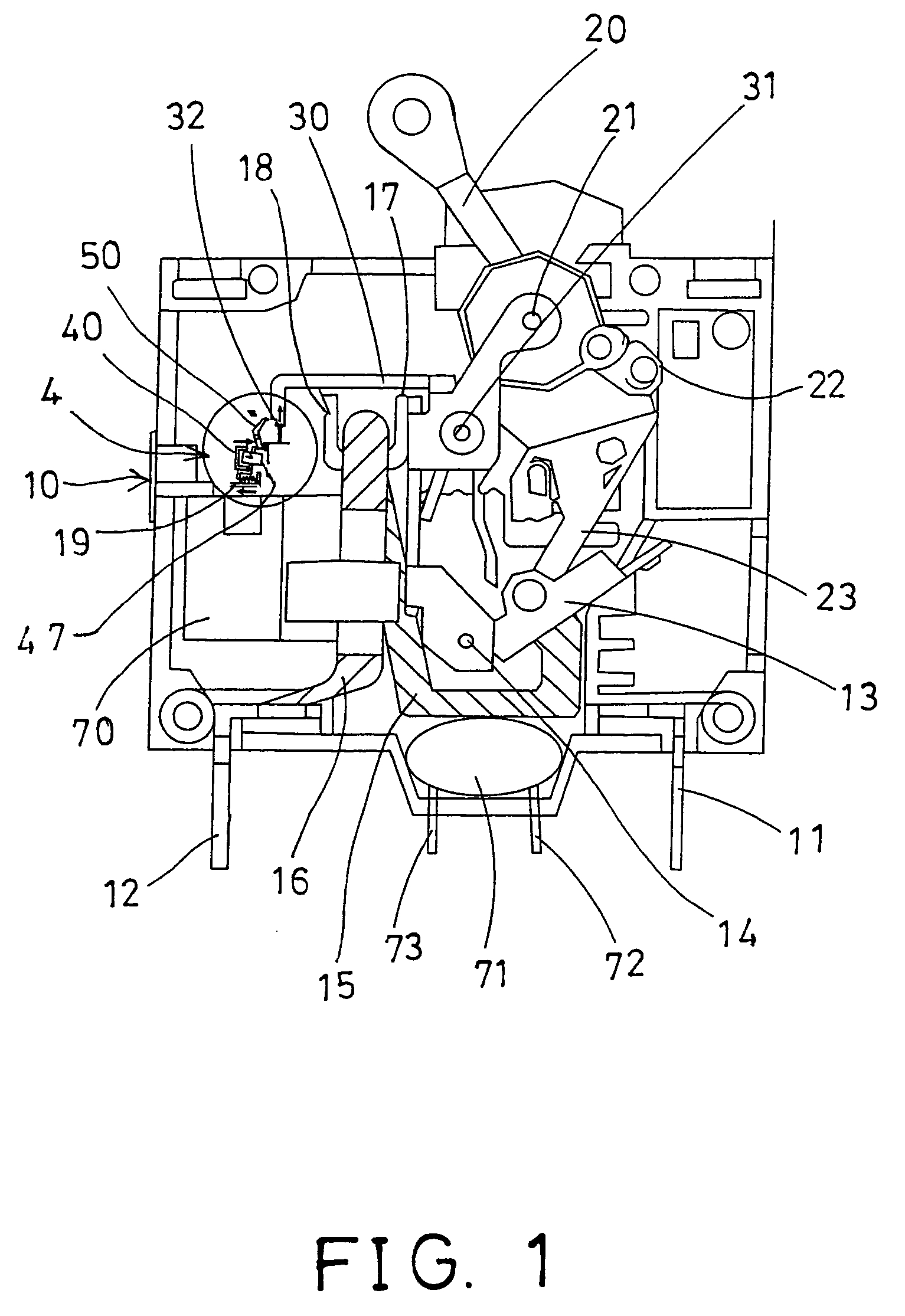
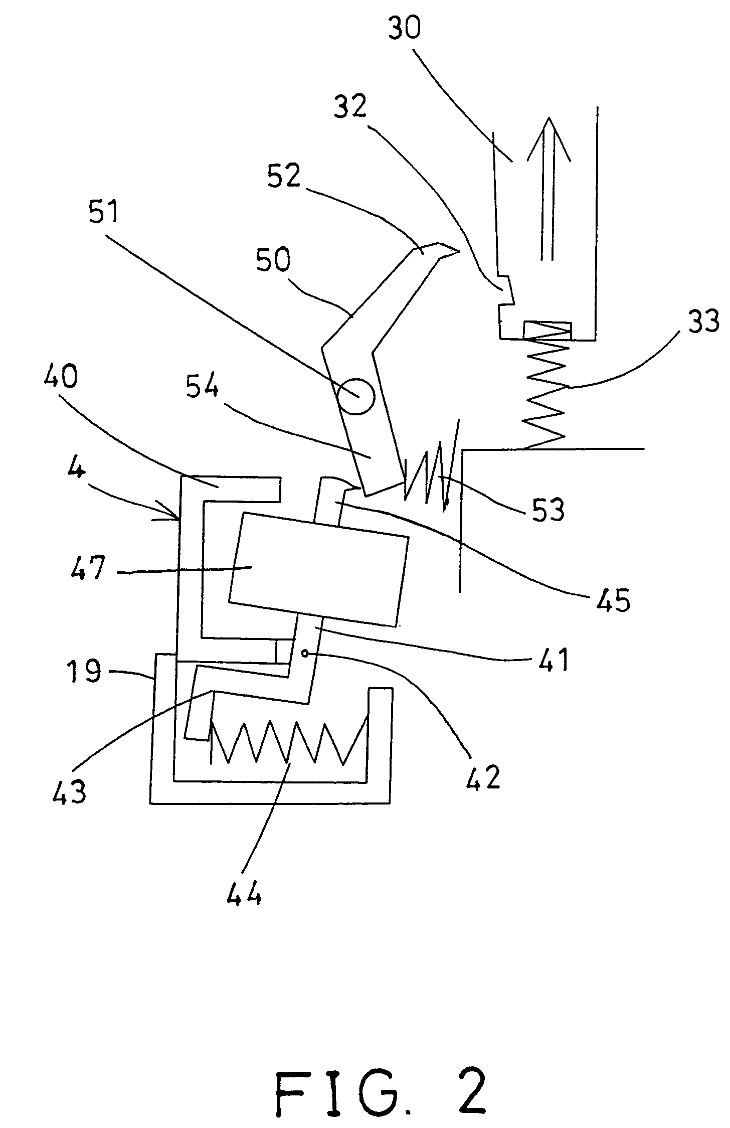
[0017]Referring to FIGS. 1 and 2, a breaker comprises a housing 10 including two terminals 11, 12 for coupling to electric facilities that are required to be protected, and a conductor 13 is rotatably supported in the housing 10 with a pivot shaft 14, and rotatable away from the terminal 11 (FIGS. 1 and 4), and rotatable to engage with the terminal 11 (FIG. 3).

[0018]Two links 15, 16 are further provided and supported in the housing 10, and electrically coupled to the conductor 13 and the terminal 12 respectively, and two further bars 17, 18 also s...


PUM


Abstract

A breaker includes a housing (10) having two terminals (11, 12), two bars (17, 18) electrically coupled to the terminals (11, 12), an arm (30) supported in the housing (10) and movable to engage with the bars (17, 18) to electrically couple the terminals (11, 12) together. A control device (4) may control the arm (30) to engage with the bars (17, 18), and includes a lever (50) to maintain the arm (30) in engagement with the bars (17, 18). A spring (33) may bias the arm (30) away from the bars (17, 18), and another spring (53) may be engaged with the lever (50) to bias and disengage the lever (50) from the arm (30).

Description

FIELD OF THE INVENTION[0001]The present invention relates to a breaker device for protecting electric facilities from being damaged when electric power supplied to the electric facilities is terminated suddenly.BACKGROUND OF THE INVENTION[0002]Various kinds of breaker devices have been developed and provided for switching off the electric facilities, and for protecting and preventing the electric facilities from being damaged when the electric power is stop supplying to the electric facilities suddenly, or when the electric power is unstable or is not good enough to energize the electric facilities.[0003]However, when the electric power is supplied to the electric facilities again, a great voltage may be generated within the electric facilities, such that the electric facilities may be easily damaged after the termination of the electric power and when the electric power is supplied to the electric facilities again.SUMMARY OF THE INVENTION[0004]It is accordingly an object of the uti...

Claims


Application Information

Patent Timeline
Patent Type & Authority Patents(United States)
IPC IPC(8): H01H9/00
CPCH01H83/12H01H53/015
Inventor CHUNG, RONG-LIN GLIN, TGO-ING
Owner CHUNG RONG LIN G
Why Eureka
Try Eureka