Abnormality diagnosis method and apparatus for gas concentration measuring device

a technology of gas concentration and diagnosis method, which is applied in the direction of electrochemical variables, instruments, electrical control, etc., can solve the problems of abnormal current flowing through the sensor element to damage the same, abnormal current cannot be determined or located by abnormal diagnosis method,

Active Publication Date: 2006-11-28
NGK SPARK PLUG CO LTD
View PDF12 Cites 28 Cited by
  • Summary
  • Abstract
  • Description
  • Claims
  • Application Information

AI Technical Summary

Benefits of technology

[0009]It is accordingly an object of the present to provide an abnormality diagnosis method and apparatus for a gas concentration measuring device, which can decide or determine, in case of occurrence of an abnormality of the gas concentration measuring device, the kind of abnormality and the place where the abnormality is caused without damaging a gas sensor of the gas concentration measuring device.
[0011]By the abnormality diagnosis method, when an abnormality is caused in the gas sensor and the voltage at one of the electrical connection points becomes equal to a predetermined abnormal voltage value, the measurement means is electrically shut off from the oxygen concentration detecting cell and the oxygen pump cell, and thereafter the abnormality diagnosis is performed. Thus, it becomes possible to prevent an abnormal current from flowing through the gas sensor subsequently after an abnormality is caused in the gas sensor and thereby prevent the gas sensor from being damaged.
[0013]The abnormality diagnosis can be performed assuredly by supplying to the oxygen concentration detecting cell and the oxygen pumping cell such a predetermined current that causes at the electrical connection points voltages larger than those produced by the oxygen concentration detecting cell and the oxygen pumping cell produce in accordance with the oxygen concentration in the measured gas space. In this connection, by supplying a minimum current necessary for the abnormality diagnosis for a necessary time, the abnormality diagnosis can be performed assuredly without damaging the gas sensor.
[0016]By performing the abnormality diagnosis after the gas sensor is determined to be abnormal, it becomes possible to dispense with the abnormality diagnosis with respect to the normal gas sensor and therefore it becomes possible to prevent the process speed of the gas concentration measuring device, from being lowered. Further, it becomes possible to eliminate unnecessary supply of current to the normal gas sensor and prevent the gas sensor from being deteriorated.
[0019]The abnormality diagnosis is thus performed after the unstable condition transiently caused by the oscillation preventing means after the gas sensor is electrically shut off from the connection points, i.e., from the measurement means, and therefore it becomes possible to perform an accurate abnormality diagnosis.
[0022]By this, in case an abnormality having been caused in the gas sensor is eliminated from some cause, measurement of a predetermined gas, concentration by the gas concentration measuring device can be restarted rapidly.

Problems solved by technology

In the meantime, in the above-described abnormality diagnosis method, the gas concentration measuring device is adapted to keep operating even in the case of occurrence of a short-circuit or the like abnormality, thus causing a possibility that an excessively large, abnormal current flows through the sensor element to damage the same.
Accordingly, the above-described abnormality diagnosis method cannot determine or locate the position where the abnormality is caused though can determine the kind of abnormality caused.

Method used


Image

  • Abnormality diagnosis method and apparatus for gas concentration measuring device
  • Abnormality diagnosis method and apparatus for gas concentration measuring device
  • Abnormality diagnosis method and apparatus for gas concentration measuring device

Examples


first embodiment

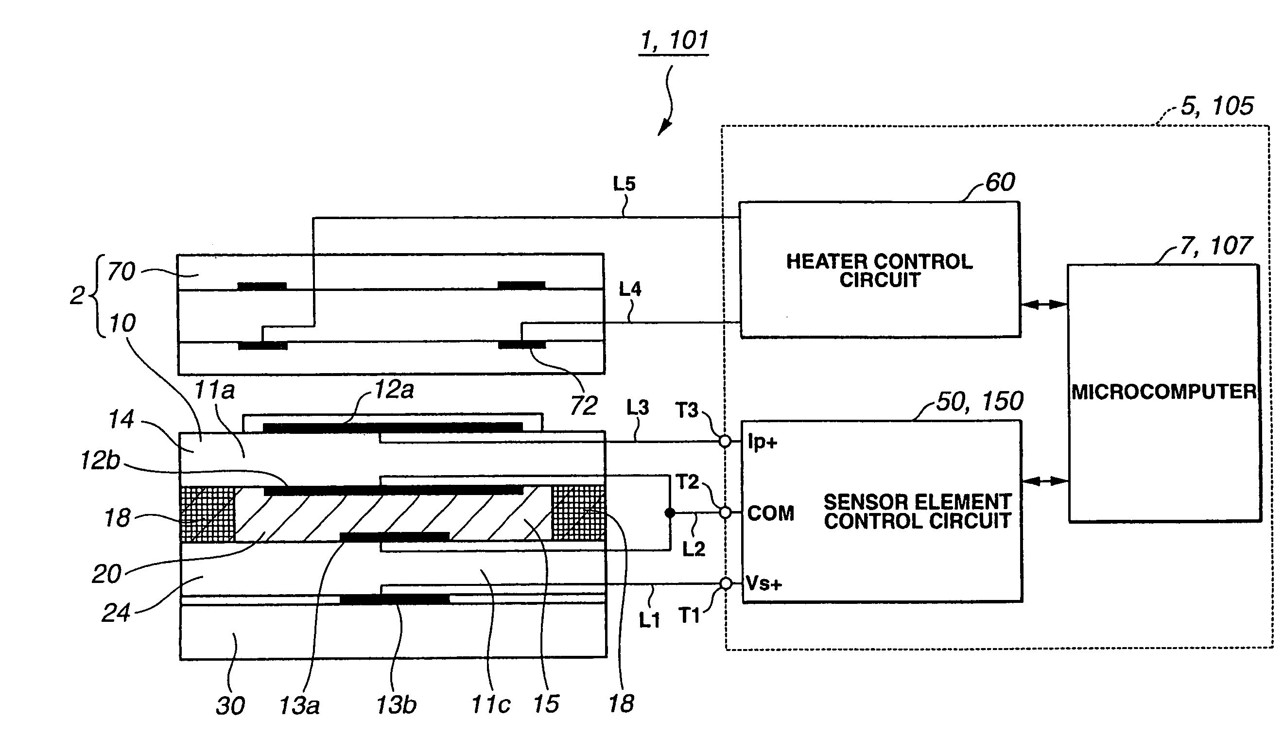
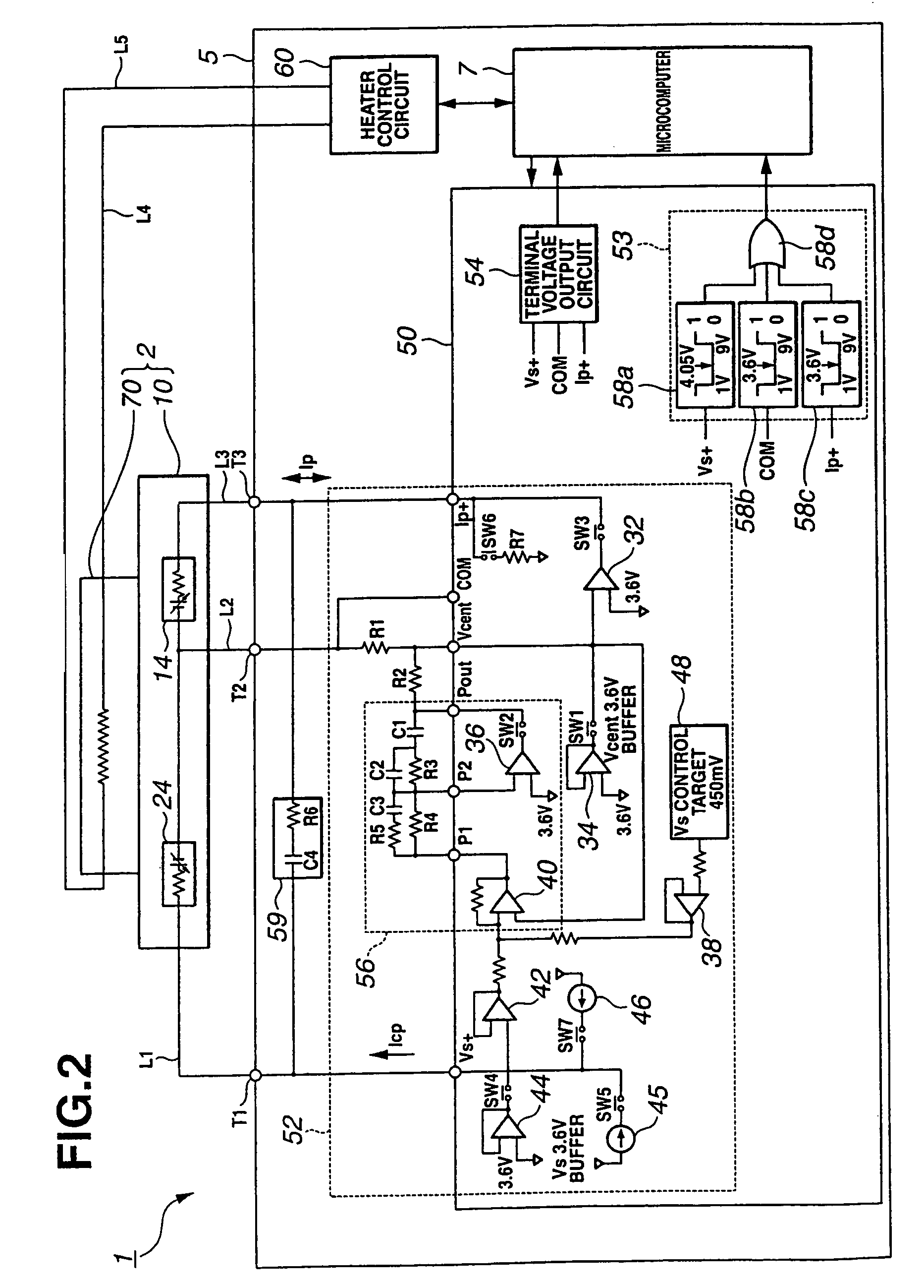
[0118]In this manner, the gas concentration measurement device 1 according to the present invention detects whether an abnormal voltage is caused at the electrical connection points (Vs+ terminal, COM terminal, Ip+ terminal) between the sensor element 10 and the sensor element drive circuit 52 by means of the wind comparators 58a, 58b and 58c. If an abnormal voltage is caused at one of the electrical connection points, the operation mode of the sensor element drive circuit 52 is switched to the protection mode to thereby electrically shut off the sensor element 10 from the sensor element drive circuit 52. Accordingly, an abnormal current does not continue flowing through the sensor element 10, thus making it possible to prevent the sensor element 10 from being damaged by the abnormal current.

[0119]Further, the gas concentration measuring device 1 of this embodiment is configured so that an abnormality determination current that is necessary for abnormality diagnosis flows through th...

second embodiment

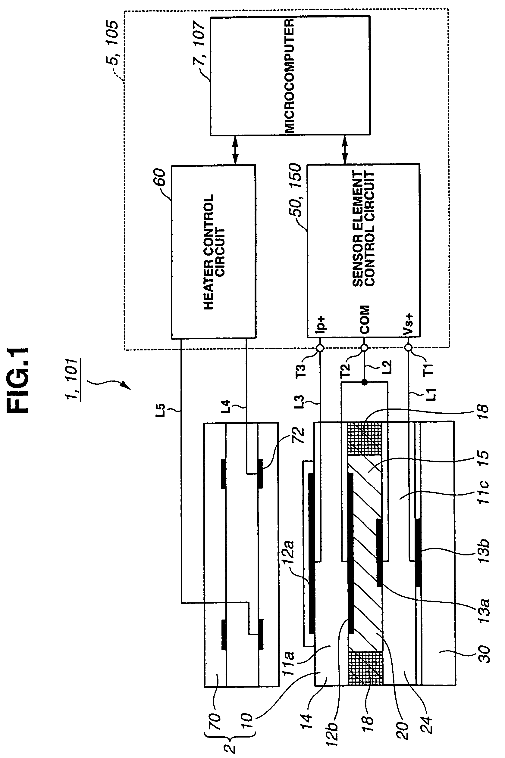
[0121]With reference to FIGS. 1 and 7 to 10, a gas concentration measuring device 101 including an abnormality diagnosis apparatus according to the present invention will be described.

[0122]The second embodiment is similar to the first embodiment so that like parts and portions will not be described again and only different portions will be described.

[0123]The gas concentration measuring device 101 of the second embodiment, similar to the gas concentration measuring device 1 in FIG. 1, includes a sensor element 10 for measuring the oxygen concentration of the measured gas in the exhaust gas, a sensor element control circuit 150 for controlling the sensor element 10, a heater 70 for holding the sensor element 10 at an activation temperature, a heater control circuit 60 for controlling the heater 70, and a microcomputer 107 for controlling the sensor element control circuit 150 and the heater control circuit 60.

[0124]In the meantime, the sensor element control circuit 150, heater cont...


PUM

PropertyMeasurementUnit
temperatureaaaaaaaaaa
electromotive forceaaaaaaaaaa
voltageaaaaaaaaaa

Abstract

An abnormality diagnosis method for a gas concentration measuring device, includes electrically shutting off measurement means from an oxygen concentration detecting cell and an oxygen pump cell of a gas sensor when a voltage at one of electrical connection points through which the measurement means is electrically connected to the oxygen concentration detecting cell and the oxygen pump cell becomes equal to a predetermined abnormal voltage value, and thereafter, electrically connecting the measurement means to the oxygen concentration detecting cell and the oxygen pump cell of the gas sensor to perform an abnormality diagnosis of the gas sensor. An abnormality diagnosis apparatus for a gas concentration measuring device is also provided.

Description

BACKGROUND OF THE INVENTION[0001]The present invention relates to an abnormality diagnosis method and apparatus for a gas concentration measuring device for use with an internal combustion engine for combustion control thereof.[0002]Heretofore, in combustion control of an internal combustion engine such as a gasoline engine for reducing CO, NOx and HC contained in the exhaust gas through control of an air-fuel ratio of a mixture of air and fuel to be supplied to the internal combustion engine, there is known such a method of feedback controlling a fuel supply amount in accordance with a concentration of a predetermined gas component contained in an exhaust gas.[0003]As a sensor used for such an air-fuel ratio control, there is known a wide-range air-fuel ratio sensor (also referred to as a UEGO sensor) in which two cells with electrodes are disposed on the opposite sides of a solid electrolytic body made of a material containing zirconia or the like as a major component in a way as ...

Claims


Application Information

Patent Timeline
Patent Type & Authority Patents(United States)
IPC IPC(8): G06F19/00F02D41/14G01N27/26F02D41/00G01N27/417
CPCG01N27/4175
Inventor INOUE, YOSHINORIIEDA, NORIKAZUTANAKA, MASAHIROKITO, REINABANNO, KEIGOHIRABAYASHI, TATSUKI
Owner NGK SPARK PLUG CO LTD
Why Eureka
Try Eureka