
Internal-combustion-engine automatic stop and restart system

a technology of automatic stop and restart, which is applied in the direction of engine starters, electric control, instruments, etc., can solve the problems of inability to restart the internal combustion engine, the pinion gear provided on the starter motor and the ring gear provided in the internal combustion engine engage with each other, and the internal combustion engine cannot be restarted, so as to prevent the calculation load on the internal combustion engine control unit from becoming excessiv

Active Publication Date: 2012-10-16
MITSUBISHI ELECTRIC CORP
View PDF8 Cites 13 Cited by
  • Summary
  • Abstract
  • Description
  • Claims
  • Application Information

AI Technical Summary

Benefits of technology

The present invention provides an internal combustion engine automatic stop and restart system that can quickly restart the engine when the restarting condition is satisfied while the engine is in an automatic stopping mode. The system includes a rotation speed calculation unit, a throttle valve, a ring gear, a pinion gear, a pinion pushing unit, a restarting control unit, and a throttle valve control unit. The system can prevent excessive calculation load on the engine control unit and minimize power consumption during the restarting process.

Problems solved by technology

Furthermore, in the conventional internal-combustion-engine automatic stop and restart system, there has been a problem that, even when the restarting condition is satisfied through the driver's operation of making the vehicle move while the internal combustion engine that has come into the automatic stopping mode inertially rotates, it is difficult to make the pinion gear provided on the starter motor and the ring gear provided in the internal combustion engine engage with each other, because there is produced a rotation-speed difference between the ring gear and the pinion gear, whereby the internal combustion engine cannot be restarted until the rotation of the internal combustion engine stops.
Accordingly, the delay of restarting hinders the driver from making the vehicle move as he likes, whereby the driver may sense discomfort.
In the conventional technology disclosed in Japanese Patent Application Laid-Open No. 2006-242082, the throttle valve is controlled even after the internal combustion engine has stopped; therefore, electric power may be consumed wastefully.
Furthermore, the control amount for the throttle valve is changed in accordance with the amount of decrease in the rotation speed of the internal combustion engine; thus, there may be caused a combustion failure, because, when there exists a restart request after the control amount for the throttle valve has been changed, the amount of air becomes too much or too small.
In addition, in the conventional technology disclosed in Japanese Patent Application Laid-Open No. 2005-113781, in the case where the fluctuation in the rotation speed of the internal combustion engine is large or the amount of decrease in the rotation speed is large, the control of the starter motor cannot keep up with the change in the rotation speed of the internal combustion engine; therefore, it may become impossible to restart the internal combustion engine while the internal combustion engine inertially rotates, because there continues the state where it is difficult for the pinion gear and the ring gear to engage with each other.
Furthermore, in the conventional technology disclosed in Japanese Patent Application Laid-Open No. 2005-113781, the starter motor is rotated in accordance with the periodic rotation fluctuation caused while the internal combustion engine inertially rotates; therefore, there exists a problem that the calculation load on the internal combustion unit becomes large, because it is required that, taking the characteristics such as the responsiveness of the starter motor into account, there is performed control of the starter motor in accordance with each of the intake stroke, the compression stroke, the power stroke, and the exhaust stroke.

Method used


Image

  • Internal-combustion-engine automatic stop and restart system
  • Internal-combustion-engine automatic stop and restart system
  • Internal-combustion-engine automatic stop and restart system

Examples


embodiment 1

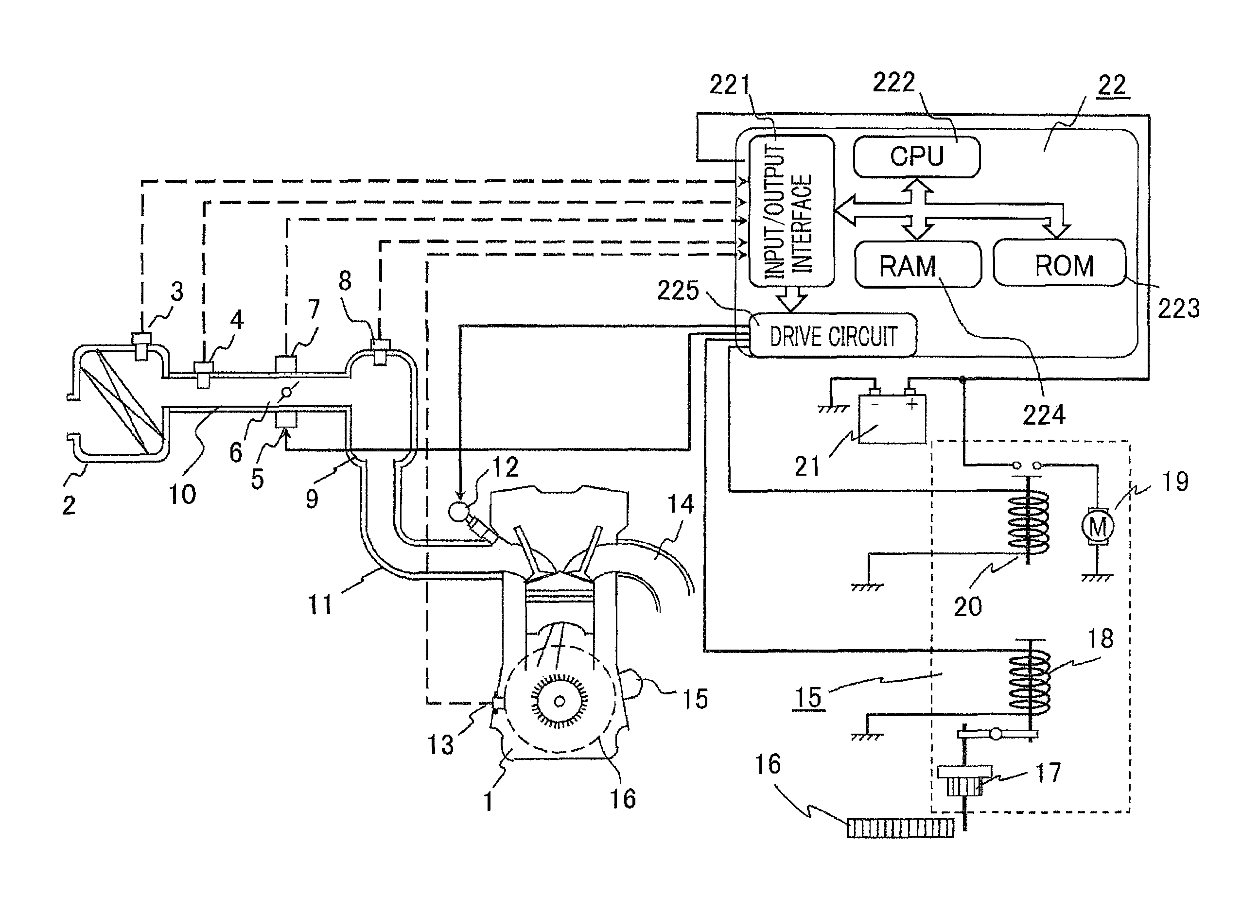
[0027]Hereinafter, an internal-combustion-engine automatic stop and restart system according to Embodiment 1 of the present invention will be explained with reference to the drawings. FIG. 1 is a configuration diagram illustrating an internal-combustion-engine automatic stop and restart system according to Embodiment 1 of the present invention. In FIG. 1, an internal combustion engine 1 is provided with an intake pipe 10 that takes in air to be supplied to the internal combustion engine 1 and an exhaust pipe 14 that exhausts exhaust air from the internal combustion engine 1. An air filter 2 is provided at the upstream side of the intake pipe 10; at the downstream side of the air filter 2, there are provided an air flow sensor 4 and an intake air temperature sensor 3 that detects the temperature of intake air. At the downstream side of the air flow sensor 4, there are provided a throttle valve 6 that adjusts the flow rate of intake air by unit of a motor 5 and a throttle opening degr...


PUM


Abstract

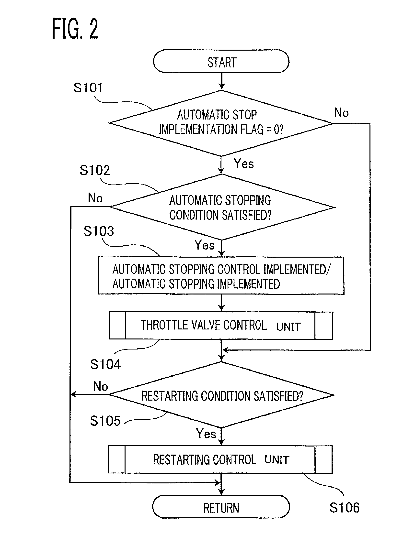
An internal-combustion-engine automatic stop and restart system performs restarting control by making the pinion pushing unit push out the pinion gear so as to engage with the ring gear, when the restarting condition is satisfied in a time period from a time when the automatic stopping condition is satisfied to a time when the rotation of the internal combustion engine stops. A throttle valve control unit opens the throttle valve even when the restarting condition has not been satisfied and stops control of the throttle valve in a time period from when the rotation of the internal combustion engine stops to when the restarting condition is satisfied, when the rotation speed of the internal combustion engine becomes lower than a predetermined value in a time period from when the automatic stopping condition is satisfied to when the rotation of the internal combustion engine stops.

Description

BACKGROUND OF THE INVENTION[0001]1. Field of the Invention[0002]The present invention relates to an internal-combustion-engine automatic stop and restart system that automatically stops an internal combustion engine when a predetermined automatic stopping condition is satisfied while the internal combustion engine is operated, and that restarts the internal combustion engine when a predetermined restarting condition is satisfied while the internal combustion engine is in the automatic stopping mode.[0003]2. Description of the Related Art[0004]In recent years, among internal combustion engines mounted in a vehicle, there has been provided an internal combustion engine in which an internal-combustion-engine automatic stop and restart system (idling stop system) is adopted for the main purpose of reducing fuel consumption. The foregoing internal-combustion-engine automatic stop and restart system is configured in such a way as to automatically stop an internal combustion engine when a ...

Claims


Application Information

Patent Timeline
Patent Type & Authority Patents(United States)
IPC IPC(8): F02D41/06
CPCF02D41/0002F02D41/042F02D41/065F02N11/0844F02N11/0855F02D2200/101F02N99/006F02N2200/022Y02T10/48Y02T10/42Y02T10/40
Inventor SHODA, TOMOHISAISHIKAWA, OSAMU
Owner MITSUBISHI ELECTRIC CORP
Learn More