Movable bed

a technology of adjustable beds and bed frames, which is applied in the direction of sofas, tables, transportation and packaging, etc., can solve the problems of affecting the comfort of users, increasing the speed of the tilting operation, and becoming the operation of the adjustable bed. , to achieve the effect of not subjecting the user to unnecessary stress

Inactive Publication Date: 2005-08-04
SANYO ELECTRIC CO LTD
View PDF15 Cites 61 Cited by
  • Summary
  • Abstract
  • Description
  • Claims
  • Application Information

AI Technical Summary

Benefits of technology

[0011] The present invention, which arose in view of the above problems, aims to provide an adjustabl

Problems solved by technology

However, the following problem exists with this conventional bed.
Since there is, with this adjustable bed, a slight amount of play in parts where the components are coupled to one another due to the nature of the manufacturing process, the relative positions of these coupling parts changes instantaneously when a load reversal as described above occurs, causing the operation of the adjustable bed to become intermittent, and resulting in jolting/jarring motion.
Also, since the compression load on elevation unit 1035L is suddenly removed, instantaneou

Method used


Image

  • Movable bed
  • Movable bed
  • Movable bed

Examples


embodiment 1

1-1. Structure of Turning Bed

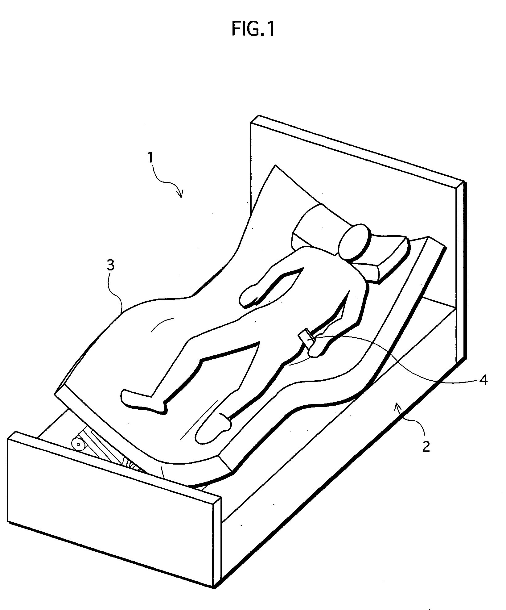
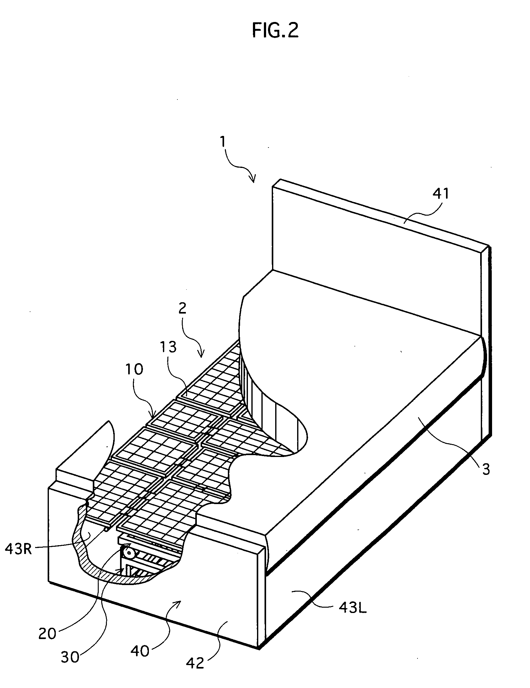
[0034]FIG. 1 is a schematic view showing a structure of a turning bed 1 pertaining to an embodiment 1. FIG. 2 is a cutaway perspective view of a section of turning bed 1.

[0035] Turning bed 1 (hereinafter, simply “bed 1”) includes, as shown in FIGS. 1 and 2, a main body 2 of the bed that includes an adjustable platform surface 13 (see FIG. 2), a mattress 3 placed on platform surface 13, and a remote controller 4 for operating platform surface 13.

[0036] By operating remote controller 4, the care recipient, for example, raises their upper body from a supine position (hereinafter, “sitting-up position”), raises their knees (hereinafter, “knee-break”), and furthermore, as shown in FIG. 1, changes their posture from a supine position to a left lateral position, for example.

[0037] Here, a posture that includes at least one of the sitting-up and knee-break positions is referred to as a “flexion position”, and the tilting of platform surface 13 of main body ...

embodiment 2

2. Embodiment 2

[0101] With the above embodiment 1, tension springs SP1R / SP1L that apply a load when the platform starts rolling so as to reduce the slope of the platform, are used as load-applying units 50. With embodiment 2, load-applying units 50 comprising tension springs SP1R / SP1L used in embodiment 1 is replaced by a load-applying unit that begins applying a load in a direction that suppresses the expansion of the slope of the platform when rolled, just before there is a reversal in the load exerted on elevation units 35R / 35L by the platform in the case of the load-applying unit being inactive.

[0102]FIG. 12 shows an overall structure of a load-applying unit in embodiment 2.

[0103] Load-applying unit 150 includes, as shown in FIG. 12, a first member and a second member that are combined so as to be freely extendable / retractable, and a compression spring, a combination of the first and second members extending with increases in the slope of the platform, and the compression spri...


PUM


Abstract

An adjustable bed including a laterally tiltable platform, a tilt mechanism that tilts the platform laterally, and a load-applying unit that applies, in a state in which the platform is tilted within a predetermined angle range during operation of the tilt mechanism, a load to the platform in a direction that suppresses an expansion of the tilt angle, so as to prevent one of a compression load and a tension load exerted on the tilt mechanism by the platform from reversing to the other load type. The adjustable bed may be structured so that the predetermined angle range includes a tilt angle at which a gravitational center of the platform during the tilt operation traverses a vertical line containing a rotational center of the platform with the load-applying unit in a non-operational state.

Description

TECHNICAL FIELD [0001] The present invention relates to adjustable beds for use in nursing care and the like, and particularly to an adjustable bed having a platform that tilts toward both sides in a width direction of the bed. BACKGROUND ART [0002] Generally, adjustable beds used as nursing-care beds (hereinafter simply “bed”) include a turning mechanism to assist in the turning of care recipients in order to prevent the occurrence of decubitus ulcers, more commonly known as bedsores. This turning mechanism operates, for example, to tilt a platform surface of the bed to both the left and right sides (width direction), and turn a care recipient lying on the bed in a direction of the incline so as to assist in postural changes. [0003]FIGS. 13A to 13C show a nursing-care bed assisting the turning of a care recipient as seen from the head end of the bed. The bed given here includes, as shown in FIG. 13A, a platform 1015 having a platform surface, and a fixed stage 1030 that supports pl...

Claims


Application Information

Patent Timeline
IPC IPC(8): A47C20/04A47C20/08A61G7/00A61G7/008A61G7/015
CPCA61G7/001A61G2203/12A61G7/015A61G7/008
Inventor KAWAKAMI, HIDEOTAGUCHI, KENJIOGAWA, ATSUSHI
Owner SANYO ELECTRIC CO LTD
Why Eureka
Try Eureka