Drill bits with reduced exposure of cutters

a cutter and drill bit technology, applied in the field of rotary drill bits, can solve the problems of bit generated by drill bits, and achieve the effects of reducing drilling difficulty, reducing drilling difficulty, and improving drilling accuracy

Inactive Publication Date: 2005-08-30
BAKER HUGHES INC
View PDF49 Cites 72 Cited by
  • Summary
  • Abstract
  • Description
  • Claims
  • Application Information

AI Technical Summary

Benefits of technology

[0009]The present invention addresses the foregoing needs by providing a well-reasoned, easily implementable bit design particularly suitable for PDC cutter-bearing drag bits, which bit design may be tailored to specific formation compressive strengths or strength ranges to provide DOC control in terms of both maximum DOC and limitation of DOC variability. As a result, continuously achievable ROP may be optimized and torque controlled even under high WOB, while destructive loading of the PDC cutters is largely prevented.

Problems solved by technology

Thus, because such cutters have a reduced amount of exposure above the respective formation-facing surface in which it is installed, especially as compared to prior art cutter installation arrangements, the resultant TOB generated by the bit will be limited to a maximum, acceptable value.

Method used


Image

  • Drill bits with reduced exposure of cutters
  • Drill bits with reduced exposure of cutters
  • Drill bits with reduced exposure of cutters

Examples


Embodiment Construction

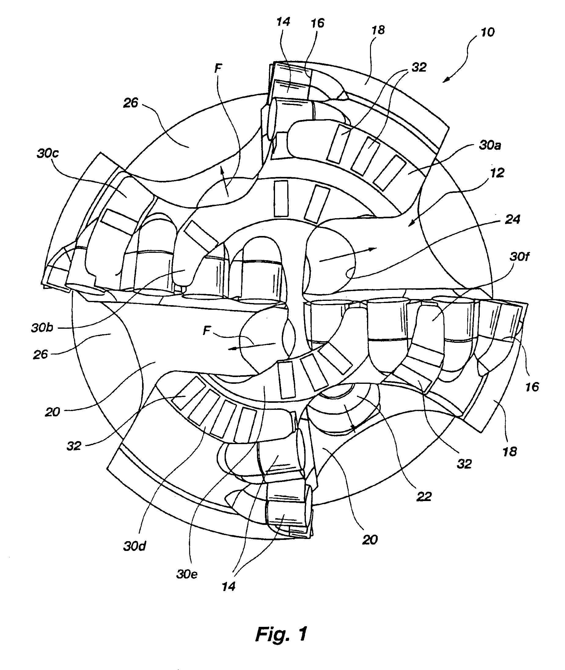
[0051]FIG. 1 of the drawings depicts a rotary drag bit 10 looking upwardly at its face or leading end 12 as if the viewer were positioned at the bottom of a borehole. Bit 10 includes a plurality of PDC cutters 14 bonded by their substrates (diamond tables and substrates not shown separately for clarity), as by brazing, into pockets 16 in blades 18 extending above the face 12, as is known in the art with respect to the fabrication of so-called “matrix” type bits. Such bits include a mass of metal powder, such as tungsten carbide, infiltrated with a molten, subsequently hardenable binder, such as a copper-based alloy. It should be understood, however, that the present invention is not limited to matrix-type bits, and that steel body bits and bits of other manufacture may also be configured according to the present invention.

[0052]Fluid courses 20 lie between blades 18 and are provided with drilling fluid by nozzles 22 secured in nozzle orifices 24, orifices 24 being at the end of pass...


PUM


Abstract

A rotary drag bit and method for drilling subterranean formations, including a bit body being provided with at least one cutter thereon exhibiting reduced, or limited, exposure to the formation, so as to control the depth-of-cut of the at least one cutter, so as to control the volume of formation material cut per bit rotation, as well as to control the amount of torque experienced by the bit and an optionally associated bottomhole assembly regardless of the effective weight-on-bit are all disclosed. The exterior of the bit preferably includes a plurality of blade structures carrying at least one such cutter thereon and including a sufficient amount of bearing surface area to contact the formation so as to generally distribute an additional weight applied to the bit against the bottom of the borehole without exceeding the compressive strength of the formation rock.

Description

CROSS-REFERENCE TO RELATED APPLICATIONS[0001]This is application is a continuation of application Ser. No. 10 / 266,534, filed Oct. 7, 2002 now U.S. Pat. No. 6,779,613, which is a continuion of application Ser. No. 09 / 738,687, filed Dec. 15, 2000, now U.S. Pat. No. 6,460,631, issued Oct. 8, 2002, which is a continuation-in-part of application Ser. No. 09 / 383,228, filed Aug. 26, 1999, now U.S. Pat. No. 6,298,930, issued Oct. 9, 2001, entitled Drill Bits with Controlled Cutter Loading and Depth of Cut.BACKGROUND OF THE INVENTION[0002]Field of the Invention: The present invention relates to rotary drag bits for drilling subterranean formations and their operation. More specifically, the present invention relates to the design of such bits for optimum performance in the context of controlling cutter loading and depth-of-cut without generating an excessive amount of torque-on-bit should the weight-on-bit be increased to a level which exceeds the optimal weight-on-bit for the current rate-o...

Claims


Application Information

Patent Timeline
Patent Type & Authority Patents(United States)
IPC IPC(8): E21B10/00E21B10/46E21B10/56E21B10/42E21B12/00E21B12/04E21B10/43E21B10/567E21B10/573
CPCE21B10/42E21B10/43E21B10/46E21B10/567E21B10/573E21B12/04E21B2010/566E21B10/5671
Inventor DYKSTRA, MARK W.HEUSER, WILLIAMDOSTER, MICHAEL L.ZALESKI, JR., THEODORE E.OLDHAM, JACK T.WATTS, TERRY D.RUFF, DANIEL E.WALZEL, RODNEY B.BEUERSHAUSEN, CHRISTOPHER C.
Owner BAKER HUGHES INC
Why Eureka
Try Eureka