High rotational speed optimized engine starter having clutch connection to engine

a high rotational speed, engine technology, applied in the direction of electric generator control, electric motor propulsion transmission, electric control, etc., can solve the problems of limiting the reduction of fuel consumption, unable to start the engine, and suspending the fuel supply

Inactive Publication Date: 2004-07-27
DENSO CORP
View PDF45 Cites 11 Cited by
  • Summary
  • Abstract
  • Description
  • Claims
  • Application Information

AI Technical Summary

Benefits of technology

In addition, the engine is able to get restarted by the engine starter before the number of the engine revolutions falls to N.sub.min, since N.sub.c is set above N.sub.min as is explained above. Therefore, the engine is restarted quickly even in the range where the engine under suspension of the fuel supply is not able to get restarted by itself by resuming of the fuel supply. As a result, a high starting response is ensured.

Problems solved by technology

However, such a system suspends the fuel supply only when the number of the engine revolutions is within a predetermined range.
Therefore, there has been a limit to the reduction of fuel consumption.
On the other hand, the engine has to be restarted by an engine starter when the fuel supply has been suspended in order to reduce the fuel consumption further until the engine revolutions fall into the range where the engine is not able to get restarted by itself by resuming of the fuel supply.
However, a pinion-plunging type starter, which is popular as an engine starter, is not able to start the engine while the engine is revolving.
As a result, starting response of the engine is not satisfactory.
However, if the number of the engine revolutions in which the one-way clutch is disconnected is below the lower limit of the engine revolutions above which the engine is able to get restarted by itself by resuming of the fuel supply, there exists a range where the engine is not able to get restarted by itself, nor by the starter.
Therefore, the engine still has a disadvantage in respect to the starting response.
Therefore, the engine is restarted quickly even in the range where the engine under suspension of the fuel supply is not able to get restarted by itself by resuming of the fuel supply.

Method used


Image

  • High rotational speed optimized engine starter having clutch connection to engine
  • High rotational speed optimized engine starter having clutch connection to engine
  • High rotational speed optimized engine starter having clutch connection to engine

Examples


first embodiment

(First Embodiment)

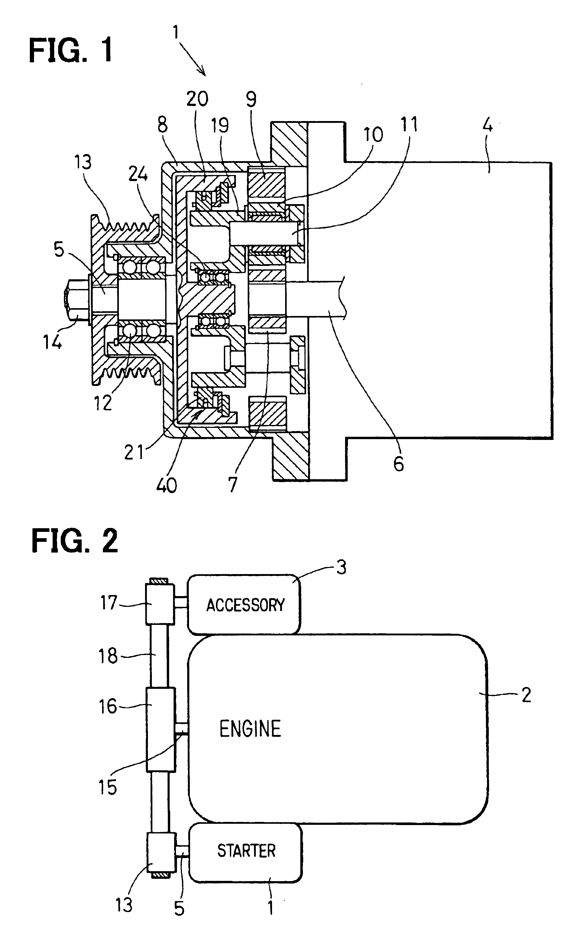
In the first embodiment shown in FIG. 1, an engine starter 1 is described. The engine starter 1 is mounted on a vehicle that has a system to suspend fuel supply to an engine 2 automatically when predetermined conditions to turn off the engine 2 are met while the vehicle is running.

As shown in FIG. 2, the engine starter 1 is not only used to start the engine 2 but also used to drive accessories 3 (a generator, a compressor for an air conditioner and the like) while the engine 2 is not operated.

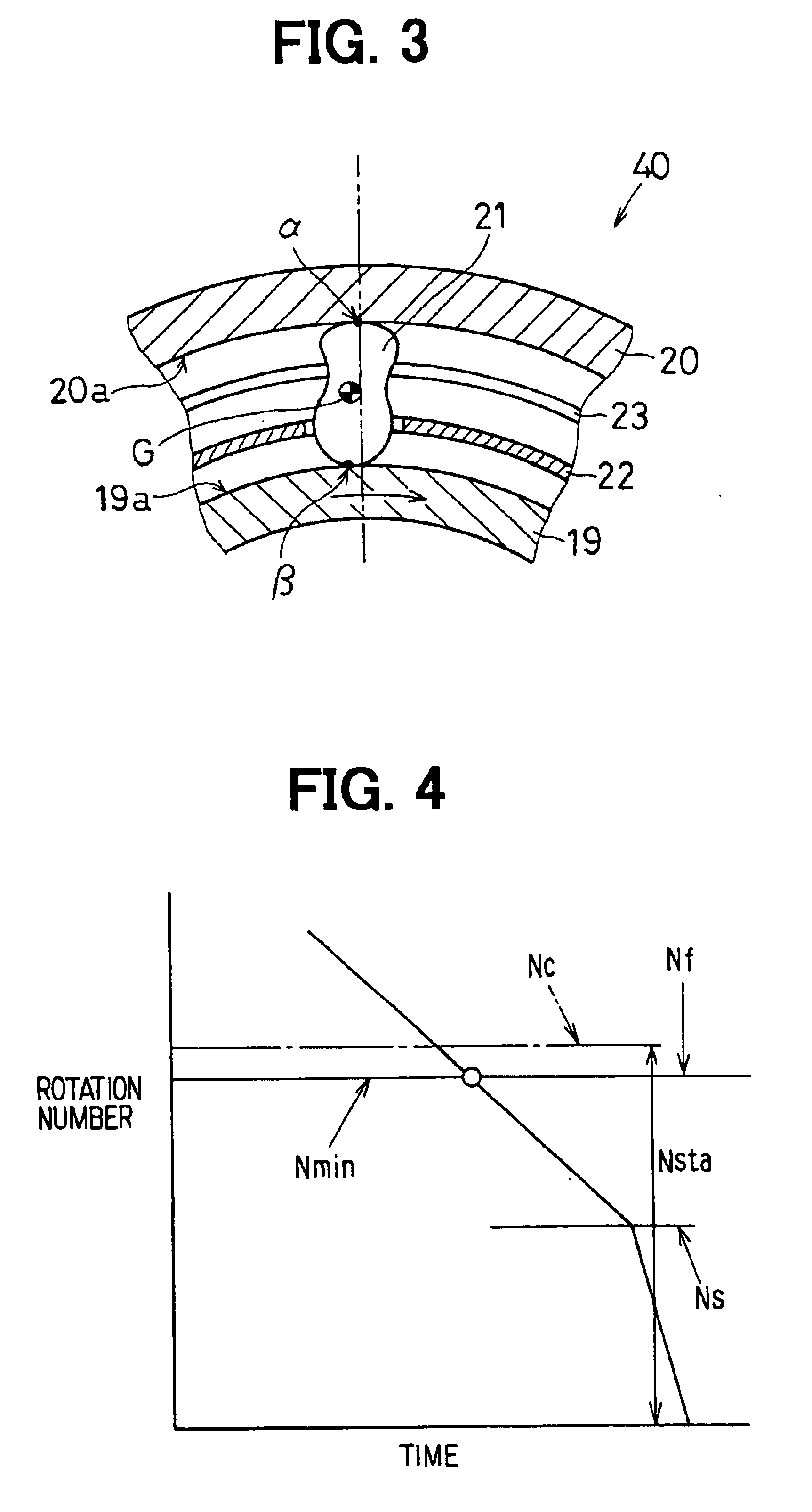
The engine starter 1 comprises a motor 4 to generate a rotating force to start the engine 2, a reduction structure (described below) to transmit the rotation of the motor 4 in reduced speeds and increased torque, a driving shaft 5 to output the rotation reduced by the reduction structure, a clutch 40 (described after) disposed between the reduction structure and the driving shaft 5, and the like.

The motor 4 is a common direct-current motor in which an armature is housed. The a...

second embodiment

(Second Embodiment)

In the second embodiment shown in FIG. 5, an engine starter 1 is described as an example that employs a roller-type one-way clutch 40, of which construction is different from the clutch 40 described in the first embodiment. A power transmission structure employs a system that transmits power through a V-belt 18 that links a driving pulley 13 and a crank pulley 16, like in the first embodiment.

The clutch 40 has an inner member 26 and an outer member 27 disposed radially inside a driving pulley 13 as shown in FIG. 5, the inner member 26 and the outer member 27 facing each other through rollers 25. The inner member 26 is fixed on the outer periphery of a rotational shaft 28 to be able to rotate together with the rotational shaft 28. The outer member 27 is formed integrally with the driving pulley 13. The rotational shaft 28 is disposed coaxially with an output shaft of a motor 4 (an armature shaft 6) through a planetary reduction device 29. The rotation of the armatu...

third embodiment

(Third Embodiment)

In the third embodiment shown in FIG. 6, an engine starter 1 is described.

The engine starter 1 is an example in which an output shaft of a motor 4 (an armature shaft 6) and a driving member 31 of a clutch 40 are linked by a gear 32 (or a torque transmission component of a belt, a chain or other kinds).

In this construction, the clutch 40 (a one-way clutch) is disposed in the side of the engine 2 (a crank pulley, a transmission case 33 and the like) not in the side of the motor 4. Accordingly, the torque transmission component such as the gear 32 linking the armature shaft 6 and the driving member 31 is stopped while the engine is not operated, which is favorable in respect of durability.


PUM


Abstract

In an engine starter of the present invention, a driving shaft to output a rotating force and a crankshaft of an engine are linked continuously. The engine starter comprises a one-way clutch to prevent an overrun of an armature after the engine starts. In the one-way clutch, a connecting rotation number in which an inner ring and an outer ring change from a disconnected state to a connected state in a decreasing process of engine revolutions is set above a lower limit of the engine revolutions above which the engine under suspension of the fuel supply is able to get restarted by itself by resuming of fuel supply. Therefore, the engine is always able to get restarted quickly even in a low-rotation range.

Description

This application is based on and incorporates herein by reference Japanese Patent Application No. 2001-277670 filed Sep. 13, 2001 and Japanese Patent Application No. 2002-126718 filed Apr. 26, 2002.1. Field of the InventionThe present invention relates to an engine starter mounted on a vehicle that has an automatic system to turn off the engine by suspending fuel supply to the engine when some predetermined conditions are met while the vehicle is running, for instances, in a constant running or in a decelerating running.2. Description of Related ArtConventionally, there has been a system to suspend fuel supply to the engine to reduce fuel consumption when some predetermined conditions are met while a vehicle is in a constant running or in a decelerating running. However, such a system suspends the fuel supply only when the number of the engine revolutions is within a predetermined range. If the engine revolutions fall below the predetermined range, the system resumes the fuel supply...

Claims


Application Information

Patent Timeline
Patent Type & Authority Patents(United States)
IPC IPC(8): F02N15/02F02N11/08F02D29/00F02D29/02F02D45/00F02N11/00F16D41/07
CPCF02N11/0844F02N15/006F02N15/023F02N15/026Y02T10/48Y02T10/40
Inventor SOUKI, TAKAHIROKATO, AKIRAKAMIYA, MASARUTANI, KEISUKEMASAKI, KAZUO
Owner DENSO CORP
Why Eureka
Try Eureka