

Hydraulic shock absorber
- Summary
- Abstract
- Description
- Claims
- Application Information
AI Technical Summary
Benefits of technology
Problems solved by technology
Method used
Image

Examples
first preferred embodiment
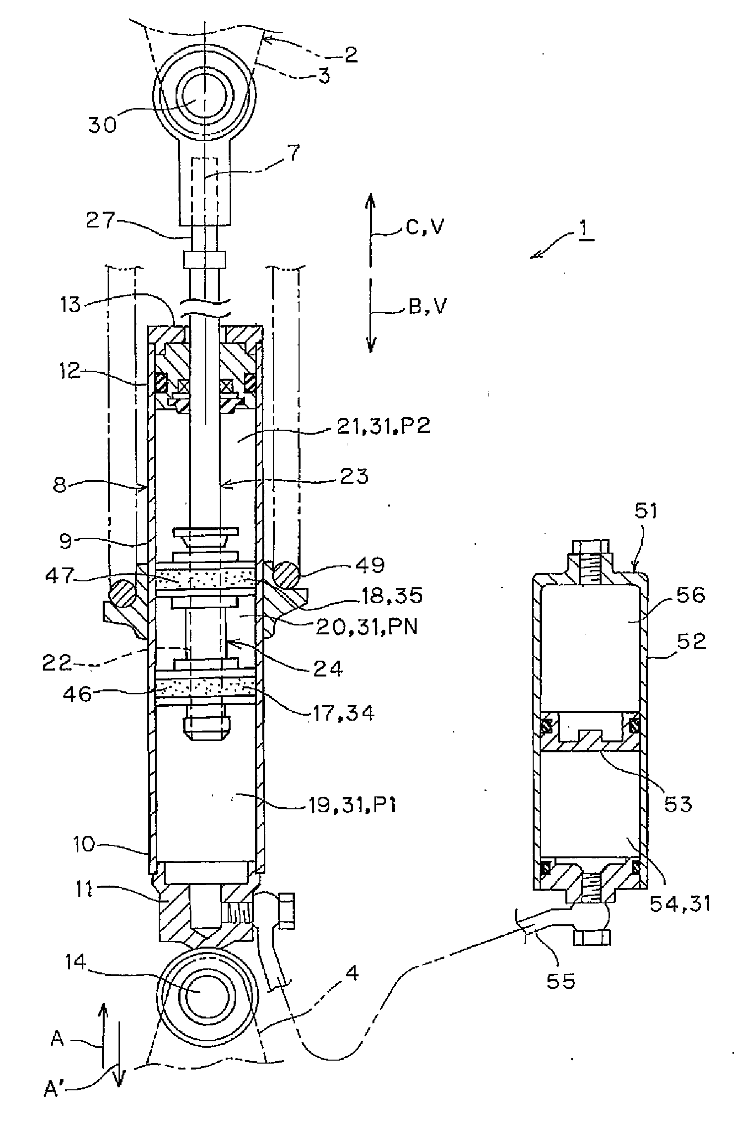
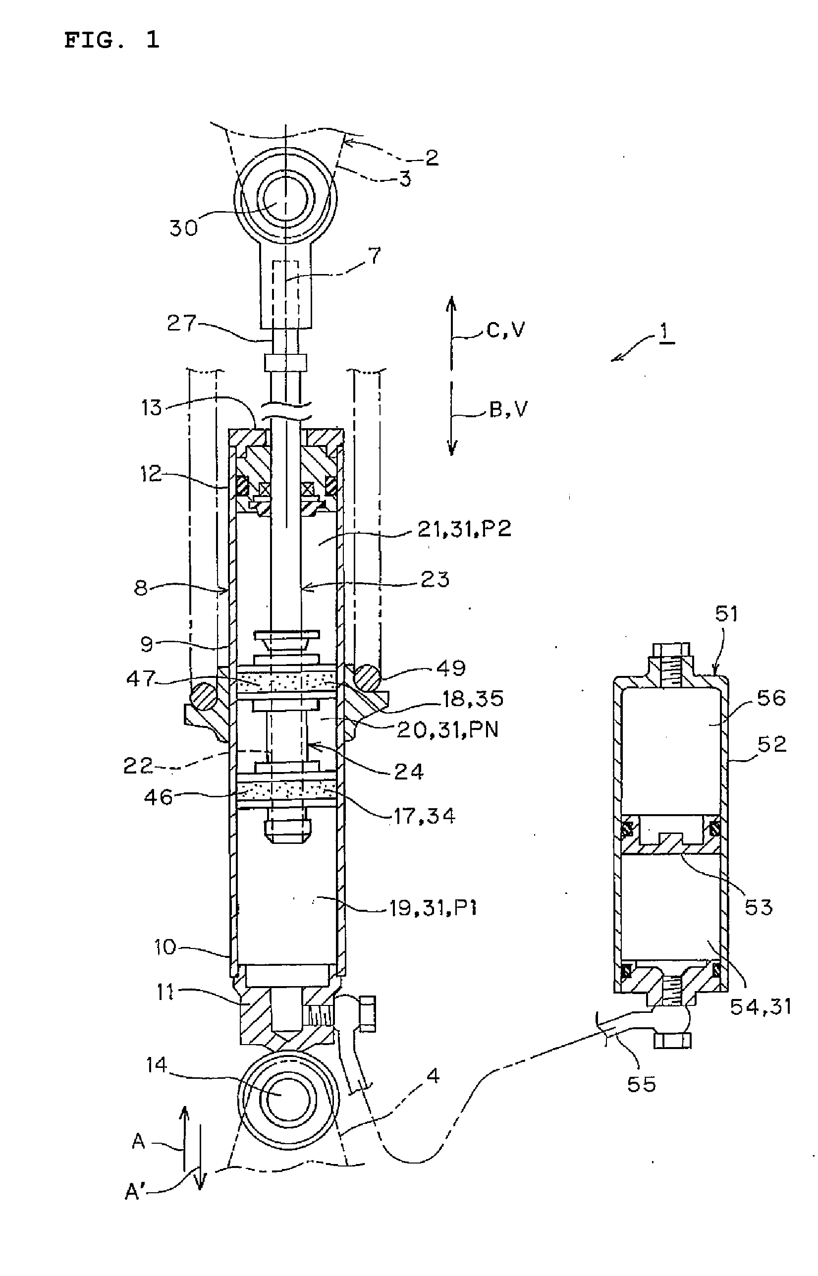
[0092]Details of the first preferred embodiment will now be described with reference to FIGS. 1 to 3 of the accompanying drawings.
[0093]The reference numeral 1 is a hydraulic shock absorber in FIGS. 1 and 2. The hydraulic shock absorber is preferably used in a suspension device of a vehicle 2, such as an automobile or a motorcycle. The hydraulic shock absorber is provided between a vehicle body side 3 of the vehicle 2 and a vehicle wheel side 4 suspended from the vehicle body side 3.
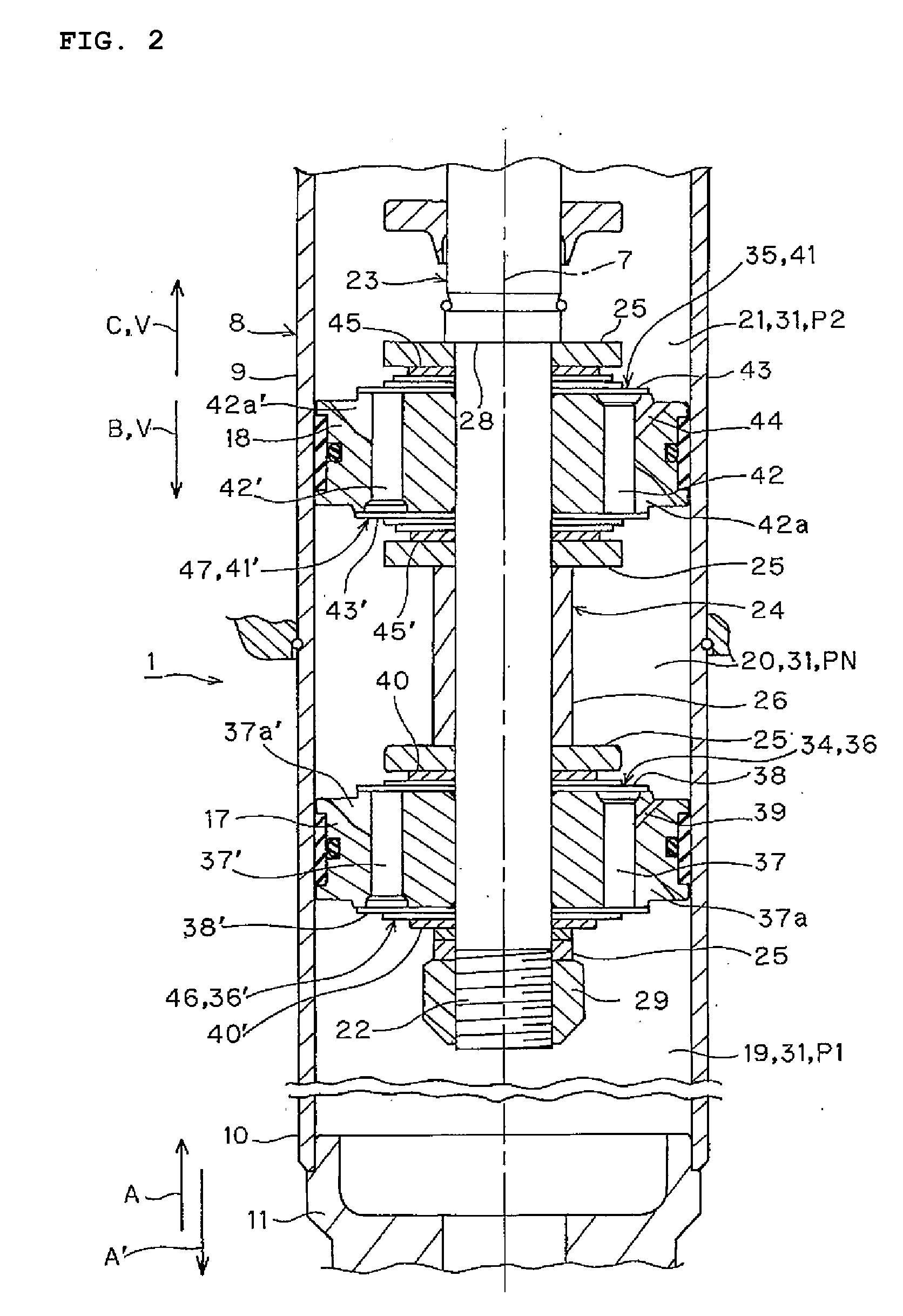
[0094]The hydraulic shock absorber 1 preferably includes a single cylinder type cylinder tube 8 that has a shaft center 7 extending in the longitudinal direction. The cylinder tube 8 includes a tube body 9 located above the shaft center 7, a cap 11 for closing the opening of the lower end of the tube body 9 which corresponds to a first end 10 of the cylinder tube 8, and a head cover 13 for closing the opening of the upper end of the tube body 9 which corresponds to a second end 12 of the cylinder tube 8....
second preferred embodiment
[0160]A detailed description of the second preferred embodiment of the present invention is now explained with respect to FIG. 4.
[0161]In FIG. 4, an intermediate piston 60 is inserted in the cylinder tube 8 such that the intermediate piston 60 can slide in the axial direction. The intermediate piston 60 is disposed between the first and the second pistons 17, 18, and connected to the piston rod 23. The intermediate chamber 20 is divided into two chambers by the intermediate piston 60. Although not shown, the pressure side and the extension side intermediate damping force generating devices, which preferably have the same configuration and effects as the extension side first damping force generating devices 34, 46, and the pressure side and extension side second damping force generating devices 35, 47, are disposed on the pressure side.
[0162]In the above case, the intermediate damping force generating device opens a valve according to the value between the first hydraulic pressure di...
third preferred embodiment
[0164]A detailed description of the third preferred embodiment of the present invention is now explained with respect to FIG. 5.
[0165]In FIG. 5, the accumulator 51 is provided in the cylinder tube 8 as a single unit. Specifically, the free piston 53 is inserted in the first chamber 19 such that the free piston 53 can slide in the axial direction. The first chamber 19 is divided into two chambers by the free piston 53. The high-pressure nitrogen gas is enclosed in the opposite chamber to the first piston 17 with respect to the free piston 53.
[0166]The shock absorber 1 can be made more compact according to the present preferred embodiment.
PUM
 Abstract
Description
Claims
Application Information