Hydraulic device for stepless transmission

a stepless transmission and hydraulic device technology, applied in the direction of clutches, fluid couplings, gearing elements, etc., can solve the problems of insufficient hydraulic oil supply to the hydraulic chamber of the pulley, insufficient hydraulic pressure in time, and insufficient hydraulic oil supply, etc., to achieve the effect of quick increase of hydraulic oil and rapid increase of hydraulic oil hydraulic pressur

Inactive Publication Date: 2012-01-19
TOYOTA JIDOSHA KK
View PDF2 Cites 13 Cited by
  • Summary
  • Abstract
  • Description
  • Claims
  • Application Information

AI Technical Summary

Benefits of technology

[0051]According to this configuration, before the hydraulic pressure of hydraulic oil to be supplied to the speed-changing hydraulic pressure circuit is increased by operating the regulator, it is possible to operate the switch-over valve and bring it into the first state in advance, and to introduce hydraulic oil discharged from the sub-pump into the main passage. Therefore, when it is predicted that the hydraulic pressure required by the speed-changing hydraulic pressure circuit increases, it is possible to operate and bring the switch-over valve into the first stage to introduce hydraulic oil discharged from the sub-pump into the main passage in advance, the regulator can be operated when the hydraulic pressure required by the speed-changing hydraulic pressure circuit increases, and it is possible to quickly increase the hydraulic pressure of hydraulic oil to be supplied to the speed-changing hydraulic pressure circuit. That is, according to this configuration, the supply paths for hydraulic oil discharged from the sub-pump can automatically be switched in accordance with the discharge performance of the main pump. When the hydraulic pressure required by the speed-changing hydraulic pressure circuit increases, it is possible to quickly increase the hydraulic pressure of hydraulic oil to be supplied to the speed-changing hydraulic pressure circuit.

Problems solved by technology

Hence, when the engine rotational speed is low and the discharge performance is low, the discharge performance of the oil pump becomes insufficient and there is an adverse possibility that a necessary amount of hydraulic oil cannot be supplied to the hydraulic chamber of the pulley.
Hence, when it is required to quickly change the speed as in a case where abrupt acceleration is requested and the hydraulic pressure required by the speed-changing hydraulic pressure circuit abruptly increases, there is an adverse possibility that the hydraulic pressure will not be increased enough in time.

Method used


Image

  • Hydraulic device for stepless transmission
  • Hydraulic device for stepless transmission
  • Hydraulic device for stepless transmission

Examples


Embodiment Construction

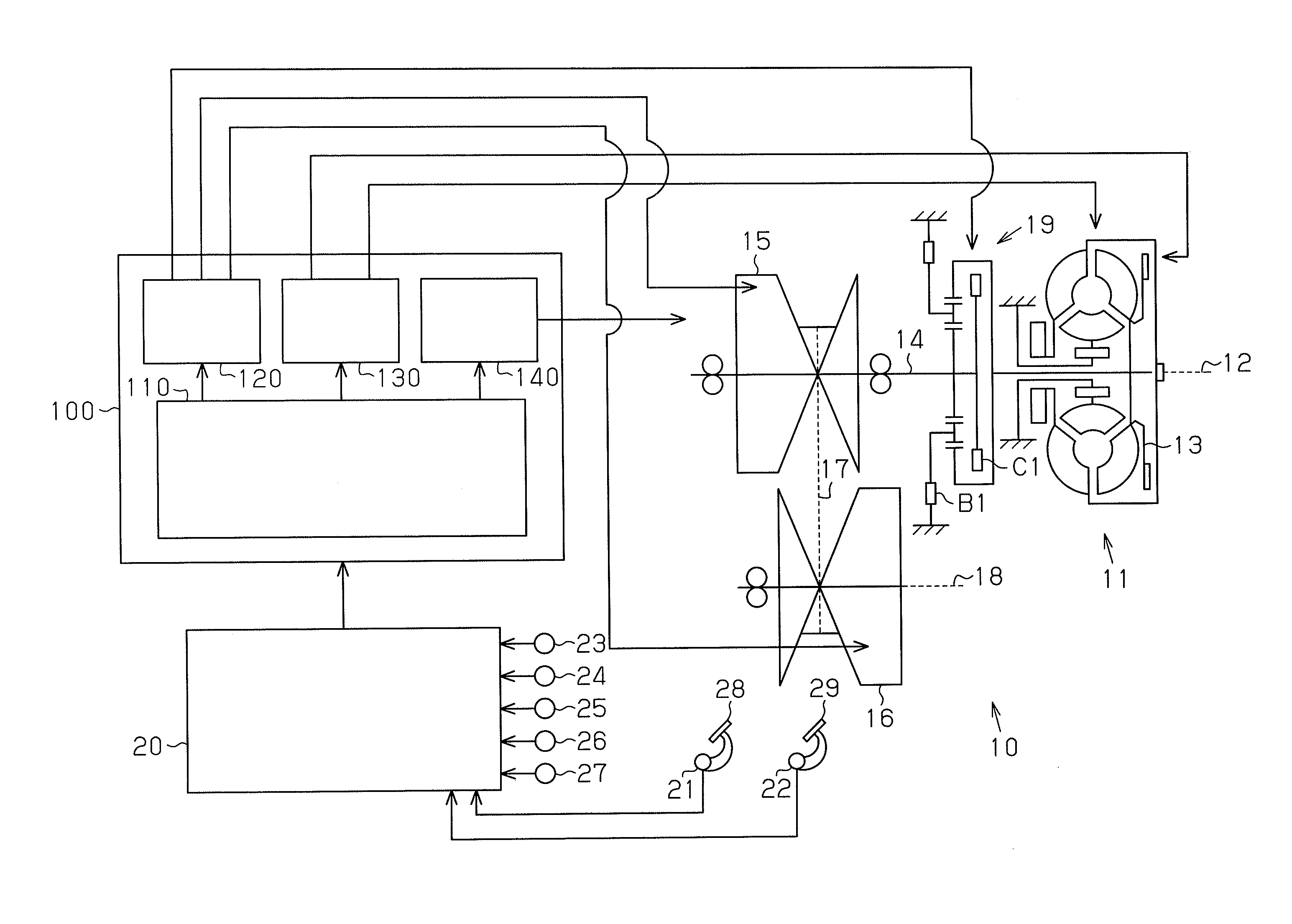
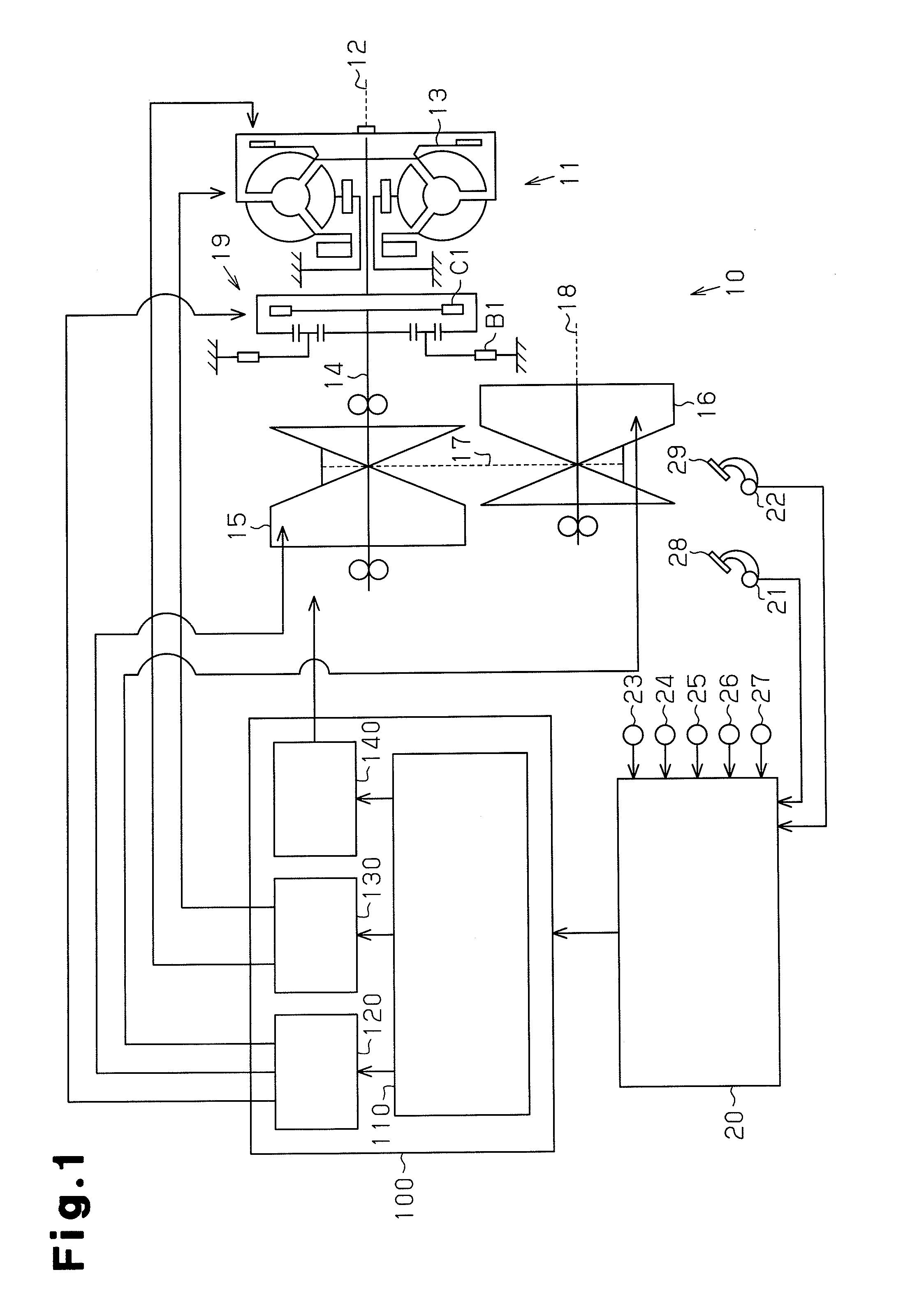
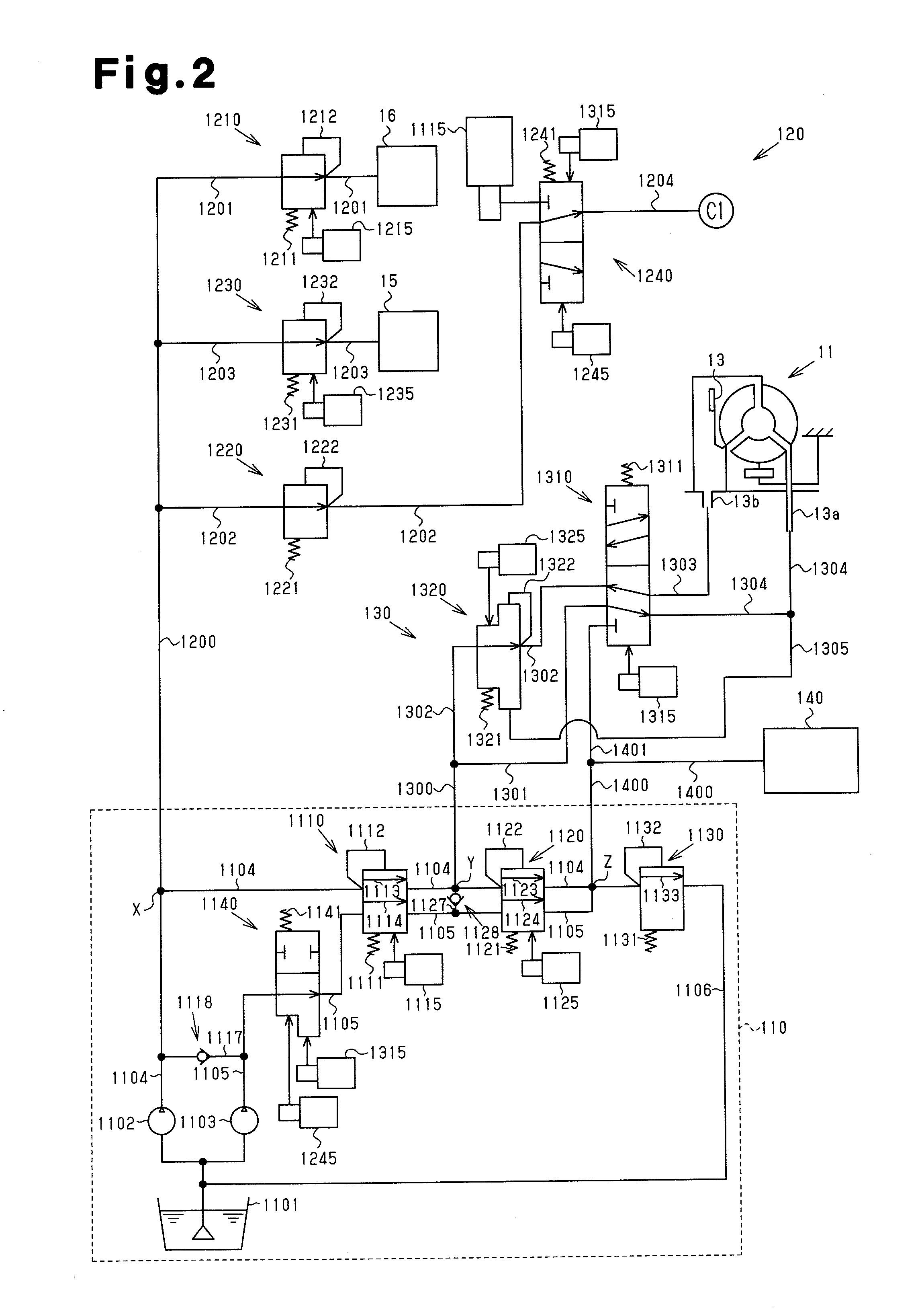
[0062]A specific embodiment of a hydraulic device for a stepless transmission mounted in an automobile according to the present invention will be described with reference to FIGS. 1 to 3. FIG. 1 is a schematic diagram of a stepless transmission including the hydraulic device according to the embodiment.

[0063]As shown in FIG. 1, a stepless transmission 10 according to the embodiment includes a torque converter 11 and a forward / reverse switching mechanism 19. An input shaft 12 of the torque converter 11 is connected to an output shaft of an internal combustion engine (not shown). The torque converter 11 includes a lockup clutch 13.

[0064]An output shaft of the torque converter 11 is connected to an input shaft of the forward / reverse switching mechanism 19. As shown in FIG. 1, the forward / reverse switching mechanism 19 includes a forward clutch C1 and a reverse brake B1 as clutches. By selectively engaging either one of the forward clutch C1 and the reverse brake B1, it is possible to s...


PUM


Abstract

A hydraulic device includes a switch-over valve 1140 provided at a section of a sub-passage 1105 located downstream of a location where a first bypass passage 1117 is connected and located upstream of a primary regulator 1110. The switch-over valve 1140 is switched between a blocked state, where supply of hydraulic oil to a section of the sub-passage 1105 located downstream of the switch-over valve 1140 is blocked, and a communication state, where supply of hydraulic oil to the section of the sub-passage 1105 located downstream of the switch-over valve 1140 is permitted. In the hydraulic device, when the switch-over valve 1140 is switched to the communication state, as a discharge performance of a main pump 1102 increases, a first check valve 1118 closes. Supply paths for hydraulic oil discharged from the sub-pump 1103 are automatically switched in accordance with the discharge performance of the main pump 1102. When the switch-over valve 1140 is switched to the blocked state, the first check valve 1118 opens and hydraulic oil discharged from the sub-pump 1103 is introduced into a main passage 1104.

Description

TECHNICAL FIELD[0001]The present invention relates to a hydraulic device for a stepless transmission.BACKGROUND ART[0002]As a stepless transmission provided in an automobile or the like, there is known a belt type stepless transmission including a primary pulley to which drive force of an internal combustion engine is transmitted, and a secondary pulley connected to vehicle wheels. The winding radius of a belt that is wound around this pair of pulleys is changed, thereby continuously changing a transmission gear ratio in a stepless manner.[0003]According to the belt type stepless transmission, the hydraulic pressure in a hydraulic chamber formed in each of the pulleys is changed to adjust the groove width of the pulley, thereby changing the winding radius of the belt, and controlling the transmission gear ratio. Hence, the belt type stepless transmission includes a hydraulic device that controls the hydraulic pressure of hydraulic oil that is supplied to the hydraulic chamber of eac...

Claims


Application Information

Patent Timeline
Patent Type & Authority Applications(United States)
IPC IPC(8): F16D31/02
CPCF16H61/0031F16H2061/66286F16H61/66259F16H61/0206
Inventor OGATA, YUSUKETANAKA, KOICHITAKAHASHI, NOBUAKIMATSUO, KENJINISHIDA, NAOFUMI
Owner TOYOTA JIDOSHA KK
Why Eureka
Try Eureka