Flameless heating system

a heating system and flameless technology, applied in the field of flameless heating systems, can solve the problem that flames cannot be used to produce heat, and achieve the effect of increasing the fluid pumping pressure of the hydraulic pump

Active Publication Date: 2016-01-05
GENERAC POWER SYSTEMS
View PDF98 Cites 15 Cited by
  • Summary
  • Abstract
  • Description
  • Claims
  • Application Information

AI Technical Summary

Benefits of technology

[0002]A mobile heating system is disclosed. In one embodiment, the system includes an enclosure supported by a mobile chassis wherein the enclosure defines an air plenum having an air inlet and an air outlet. The system also includes a fan disposed in the air plenum wherein the fan is configured to move an air flow stream from the air inlet to the air outlet of the enclosure. An internal combustion engine is also disposed in the air plenum. The heating system also includes a hydraulic circuit including a hydraulic pump operably coupled to the output shaft of the internal combustion engine, and a first heat exchanger located in the enclosure air plenum and in fluid communication with the hydraulic pump. The first heat exchanger is configured to transfer heat from fluid in the hydraulic circuit to the air flow stream. The hydraulic circuit also includes a hydraulic motor operably coupled to the fan wherein the hydraulic motor is in fluid communication with and driven by the hydraulic pump. A first valve is disposed between the hydraulic pump and the heat exchanger and is configured to restrict fluid flow and to increase a fluid pumping pressure of the hydraulic pump. A second valve is located upstream of the first valve and is configured to selectively direct hydraulic fluid between the first valve and the hydraulic motor. In one embodiment, the system further includes a control system configured to operate the second valve to maintain a temperature set point of the air flow stream.

Problems solved by technology

However, in some instances, such as oil wells, a flame cannot be used to produce the heat due to safety concerns.

Method used


Image

  • Flameless heating system
  • Flameless heating system
  • Flameless heating system

Examples


examples

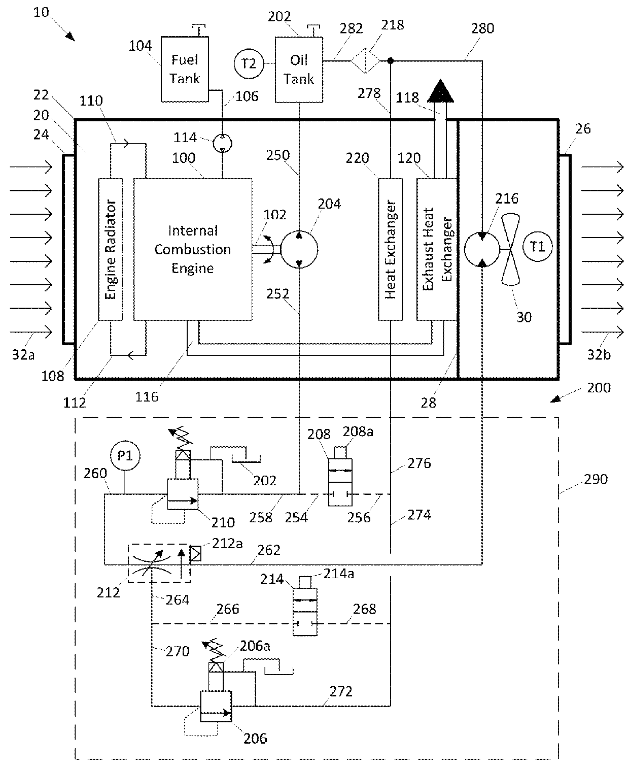
[0055]In one example of an optimized system, the flameless heating system 10 can be configured to heat an ambient airflow stream 32a from 0 degrees F. to 180 degrees F. at a volumetric flow rate of 1,200 cubic feet per minute. These conditions correspond to an overall heating output for the flameless heating system 10 of about 200,000 BTH / hour.

[0056]To achieve this output, a 1.5 liter diesel engine consuming about 1.8 gallons of fuel per hour is selected. In this state, the engine 100 is providing approximately 25 horsepower at a rotational speed of about 2,500 rpm while radiating about 18,000 BTU / hour into the plenum 20. Additionally, the radiator 108 will add approximately 64,000 BTU / hour to the plenum 20 under these conditions wherein the entering coolant temperature is about 180 degrees F., the leaving coolant is about 170 degrees F., and the coolant flow rate is about 14 gpm. Finally, the engine exhaust heat exchanger 120 will add approximately 26,000 BTU / hour wherein the enter...


PUM


Abstract

A mobile heating system is disclosed. In one embodiment, the system includes an enclosure defining a plenum that houses a fan and an internal combustion engine. The heating system also includes a hydraulic circuit including a hydraulic pump operably coupled to the internal combustion engine and a first heat exchanger located in the plenum and in fluid communication with the hydraulic pump. The hydraulic circuit also includes a hydraulic motor operably coupled to the fan wherein the hydraulic motor is in fluid communication with and driven by the hydraulic pump. A first valve is disposed between the hydraulic pump and the heat exchanger and is configured to restrict fluid flow and to increase a fluid pumping pressure of the hydraulic pump. A second valve is located upstream of the first valve and is configured to selectively direct hydraulic fluid between the first valve and the hydraulic motor.

Description

BACKGROUND[0001]Industrial heaters are used in a wide variety of situations, including outdoor construction, oil drilling, airports, unheated buildings, etc. Most industrial heaters utilize an internal combustion engine along with a combustion-type generator or burner which uses a flame to produce heat. However, in some instances, such as oil wells, a flame cannot be used to produce the heat due to safety concerns. In such instances, flameless heaters have been developed. However, improvements in flameless heater technology are desired, particularly with regard to efficiency.SUMMARY[0002]A mobile heating system is disclosed. In one embodiment, the system includes an enclosure supported by a mobile chassis wherein the enclosure defines an air plenum having an air inlet and an air outlet. The system also includes a fan disposed in the air plenum wherein the fan is configured to move an air flow stream from the air inlet to the air outlet of the enclosure. An internal combustion engine...

Claims


Application Information

Patent Timeline
Patent Type & Authority Patents(United States)
IPC IPC(8): B60H1/02F24H9/20F24H1/00F24H3/08F24H1/06B60H1/00B60H1/03B60H1/20F24D1/04B60H1/14F24J3/00F24H1/08
CPCF24H9/2064B60H1/00314B60H1/038F24H1/009F24H1/06F24H3/08B60H2001/146F24H1/08F24J3/006F24V40/10F24H15/31F24H15/414F24H15/242F24H15/345F24H15/281F24H15/238F24H15/208
Inventor WELLE, TRAVIS G.LEINGANG, MARK R.
Owner GENERAC POWER SYSTEMS
Why Eureka
Try Eureka