Power transfer mechanism control device and power transfer device

a technology of power transfer mechanism and control device, which is applied in the direction of machines/engines, engine starters, transportation and packaging, etc., can solve problems such as vehicle shock, and achieve the effect of suppressing torque variation transfer

Inactive Publication Date: 2011-09-29
AISIN AW CO LTD
View PDF9 Cites 13 Cited by
  • Summary
  • Abstract
  • Description
  • Claims
  • Application Information

AI Technical Summary

Benefits of technology

[0016]Because the power transfer device according to the present invention includes the power transfer mechanism control device according to any one of the aspects of the present invention discussed above, the power transfer device according to the present invention can achieve the effect achieved by the power transfer mechanism control device according to the present invention. For example, the power transfer device according to the pres

Problems solved by technology

The setting of the standby pressure applied to the clutch while the engine is stationary can be considered as an important issue for further improving the starting performance of a vehicle by quickly transferring power of the

Method used


Image

  • Power transfer mechanism control device and power transfer device
  • Power transfer mechanism control device and power transfer device
  • Power transfer mechanism control device and power transfer device

Examples


Embodiment Construction

[0032]An embodiment of the present invention will be described below.

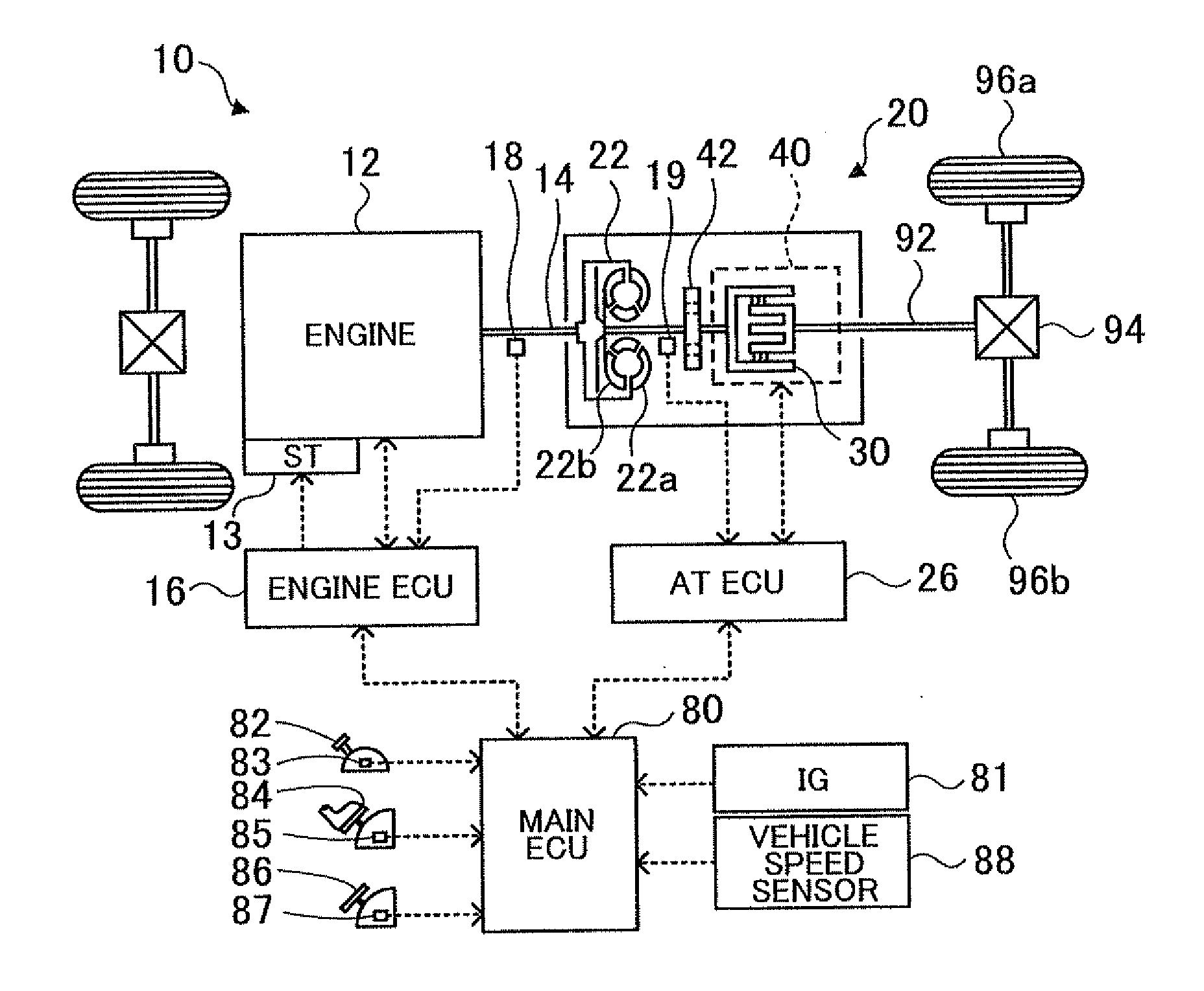
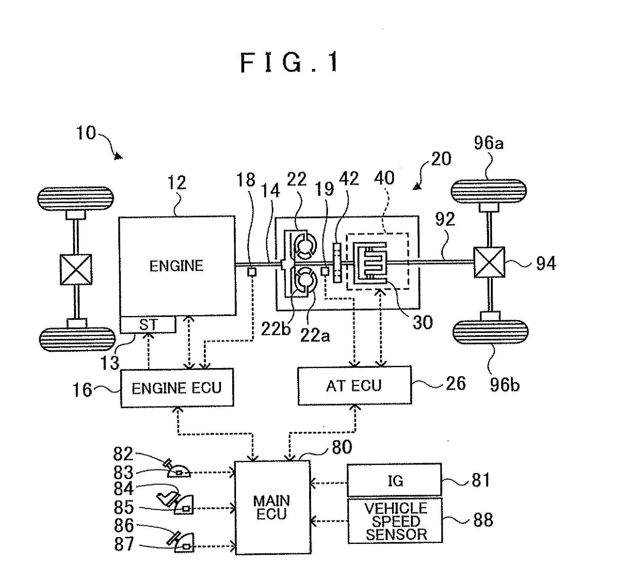
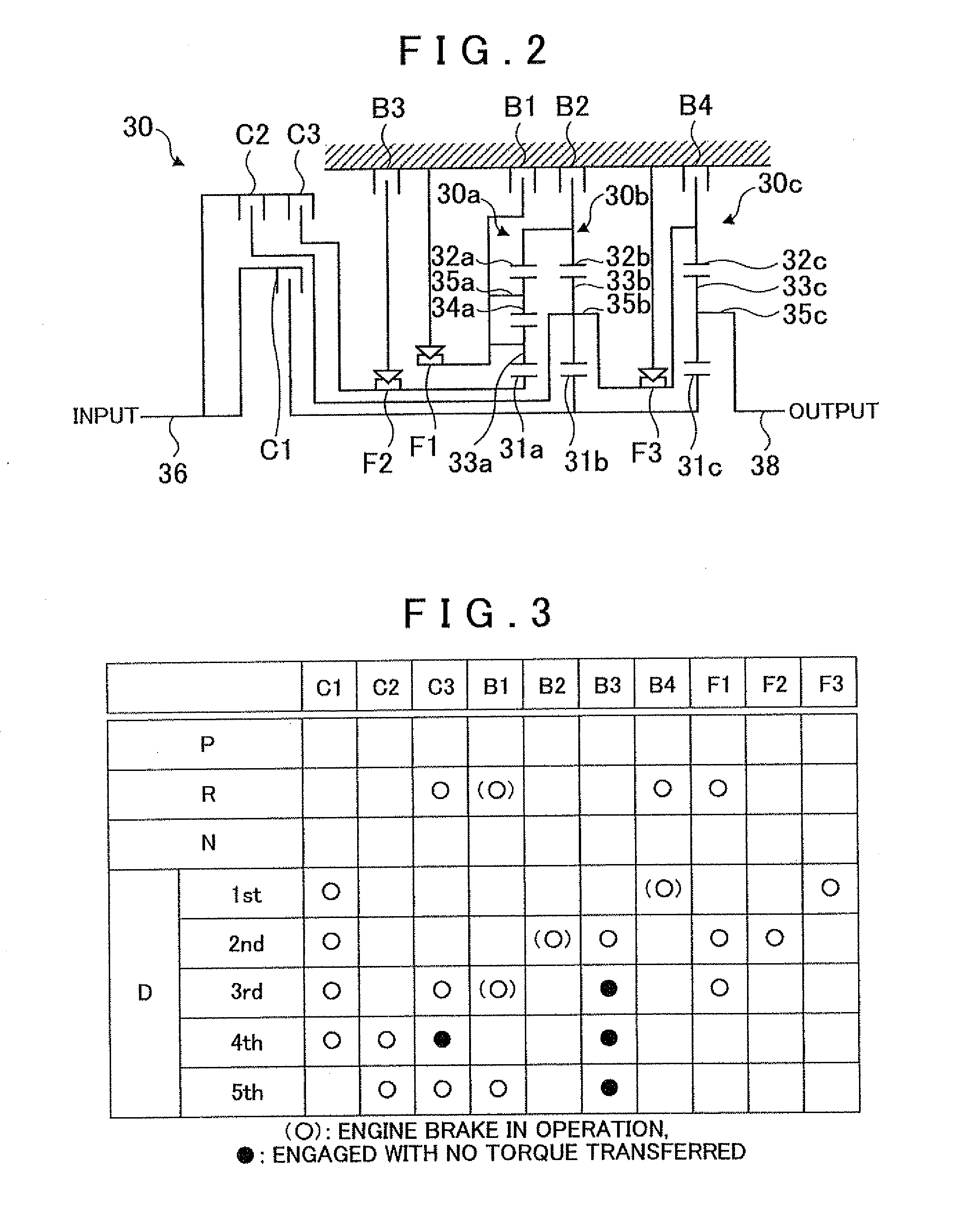
[0033]FIG. 1 is a diagram showing a schematic configuration of an automobile 10 incorporating a power transfer device 20 according to the embodiment of the present invention. FIG. 2 is a diagram showing a schematic configuration of an automatic transmission 30 provided in the power transfer device 20 according to the embodiment. FIG. 3 shows an operation table of the automatic transmission 30.

[0034]As shown in FIG. 1, the automobile 10 according to the embodiment includes an engine 12 which is an internal combustion engine that outputs power generated by explosive combustion of a hydrocarbon fuel such as gasoline and diesel oil, and the power transfer device 20 according to the embodiment which is connected to a crankshaft 14 of the engine 12 and connected to a drive shaft 92 coupled to left and right wheels 96a and 96b via a differential gear 94 to transfer the power from the engine 12 to the drive shaft 92.

[0035]...


PUM


Abstract

A power transfer mechanism control device controlling a power transfer mechanism mounted on a vehicle which transfers power from an internal combustion engine to an axle side via a friction engagement element actuated by a fluid pressure from either of a first fluid pressure actuator driven by the power from the internal combustion engine and a second fluid pressure actuator driven by a fluid pressure source different from a fluid pressure source for the first fluid pressure actuator. When the internal combustion engine is to be automatically started, the second fluid pressure actuator is controlled such that, before complete combustion occurs in the internal combustion engine, the friction engagement element stands by in a low-pressure state, and the first fluid pressure actuator is controlled such that the friction engagement element transfers the torque at predetermined timing after the complete combustion occurs in the internal combustion engine.

Description

INCORPORATION BY REFERENCE[0001]The disclosure of Japanese Patent Application No. 2010-075579 filed on Mar. 29, 2010 including the specification, drawings and abstract is incorporated herein by reference in its entirety.BACKGROUND OF THE INVENTION[0002]The present invention relates to a power transfer mechanism control device controlling a power transfer mechanism which is mounted on a vehicle including an automatically stoppable and automatically startable internal combustion engine and which transfers power from the internal combustion engine to an axle side via a friction engagement element actuated by a fluid pressure from either of a first fluid pressure actuator driven by the power from the internal combustion engine and a second fluid pressure actuator driven by a fluid pressure source different from that for the first fluid pressure actuator, and also relates to a power transfer device including a power transfer mechanism and a control device that controls the power transfer...

Claims


Application Information

Patent Timeline
IPC IPC(8): B60K23/02B60W10/02B60W10/06B60W50/00
CPCB60W10/02B60W10/06B60W30/192B60W2710/027Y10T477/669F16H2312/022F16H2312/14Y10T477/71Y10T477/673F16H61/0031
Inventor HIRAI, NOBUYUKISHIMIZU, TETSUYATSUCHIDA, KENICHIISHIKAWA, KAZUNORIISHIBASHI, ATSUSHI
Owner AISIN AW CO LTD
Why Eureka
Try Eureka