Vehicle front body structure

Inactive Publication Date: 2005-04-21
HONDA MOTOR CO LTD
View PDF5 Cites 18 Cited by
  • Summary
  • Abstract
  • Description
  • Claims
  • Application Information

AI Technical Summary

Benefits of technology

[0012] As described above, in this invention, using the reinforcing member, the longitudinally extending closed-section portions are formed along the right and left upper portions of the extension of the crossmember and the front end portion of the floor tunnel, respectively, and the right closed-section portions and the left closed-section portions are connected to one another, so that the rigidity of the joined portion of the floor tunnel to the extension can be increased. Consequently, collision energy acting from the

Problems solved by technology

However, there is a limit on efficient absorption of colli

Method used


Image

  • Vehicle front body structure
  • Vehicle front body structure
  • Vehicle front body structure

Examples


Example

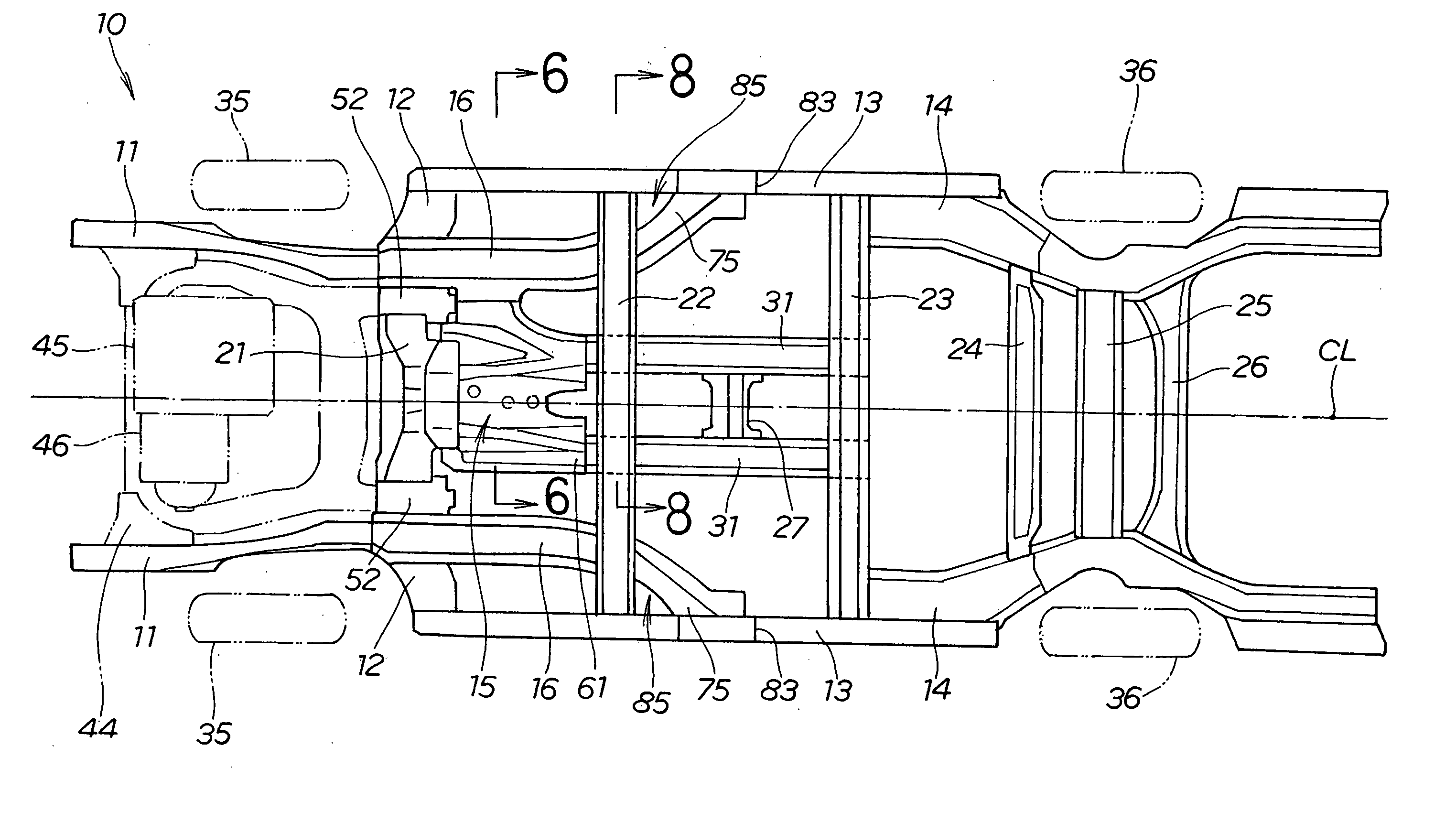
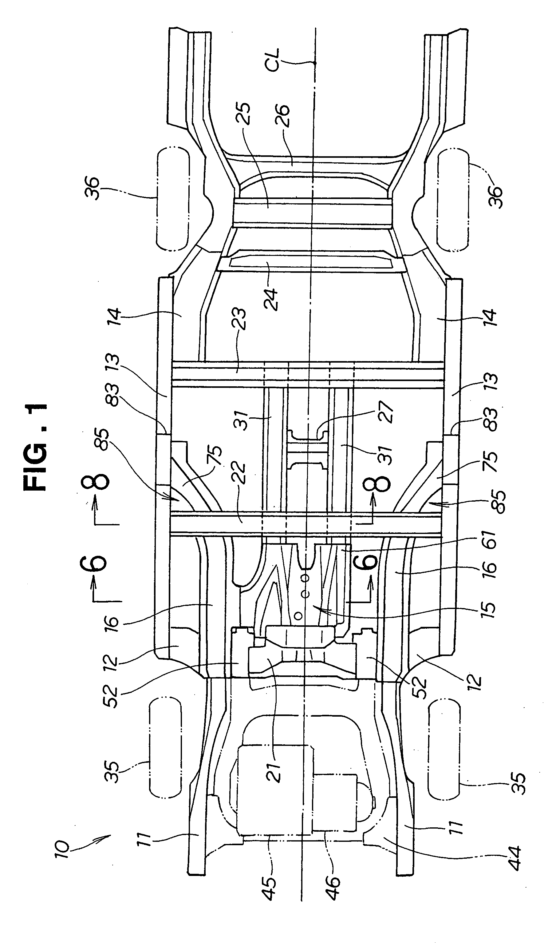
[0035]FIG. 1 shows a vehicle body 10 with a floor panel removed, but a floor tunnel 15 is shown for convenience of description. Throughout the drawings the terms “front,”“rear,”“right” and “left” represent directions as viewed from a driver.

[0036] Referring to FIG. 1, the vehicle body 10 is a low-floor type vehicle body with a floor panel reduced in height. The vehicle body 10 is comprised of a vehicle frame mainly including front side members 11, 11, right and left side outriggers 12, 12, right and left side sills 13, 13, right and left rear side members 14, 14, a floor tunnel 15, floor frame members 16, 16, and crossmembers 21 to 26.

[0037] The right and left front side members 11, 11 are disposed at the front of the vehicle body 10, extending longitudinally of the vehicle body 10.

[0038] The right and left side outriggers 12, 12 are joined to rear side portions of the right and left front side members 11, 11.

[0039] The right and left side sills 13, 13 extend rearward from rear ...


PUM


Abstract

A front part structure of a vehicle body for efficiently absorbing collision energy acting from the front of the vehicle body is provided. The front part structure of the vehicle body includes right and left front side members extending longitudinally of the vehicle body within an engine compartment separated by a dashboard. A crossmember is attached to the dashboard and extended between the right and left front side members. A floor tunnel extending longitudinally of the vehicle body is joined to a rear end portion of an extension of the crossmember. Collision energy acting from the front of the vehicle body is transmitted from the front side members to the crossmember, and then is transmitted through the extension of the crossmember to the floor tunnel and dispersed throughout the vehicle body.

Description

FIELD OF THE INVENTION [0001] The present invention relates to a front part structure of a vehicle body, and more particularly, to an improvement in a dashboard portion. BACKGROUND OF THE INVENTION [0002] A front part structure of a vehicle body in which a crossmember is provided at a dashboard is disclosed in Japanese Patent Laid-Open Publication No. HEI-10-7022, for example. This vehicle front body structure will be described with reference to FIGS. 19 and 20 hereof. [0003] As shown in FIGS. 19 and 20, a vehicle body 200 is partitioned into an engine compartment 202 and a passenger compartment 203 by a dashboard 201. The dashboard 201 is formed at its bottom central portion with a hollow tunnel 204 extending fore and aft of the dashboard 201. A crossmember 205 is joined along the bottom of the dashboard 201. A propeller shaft and a muffler (not shown) are extended through the tunnel 204. [0004] Generally, rearward of the tunnel 204 is provided a floor tunnel extending longitudinal...

Claims


Application Information

Patent Timeline
IPC IPC(8): B62D21/15B62D25/08B62D25/20
CPCB62D21/152B62D25/025B62D25/2045B62D25/2018B62D25/2036B62D25/082
Inventor AKASAKA, KOSUKE
Owner HONDA MOTOR CO LTD
Why Eureka
Try Eureka