Method and apparatus for the distribution of brake torque on a vehicle

a technology for distributing brake torque and vehicles, which is applied in mechanical equipment, braking systems, transportation and packaging, etc., can solve the problems of reducing braking capacity, reducing safety margins, and reducing oil flow retardation, so as to increase the overall braking performance of the vehicle, maximize the speed of the vehicle, and reduce the effect of safety margins

Inactive Publication Date: 2006-06-01
VOLVO LASTVAGNAR AB
View PDF8 Cites 18 Cited by
  • Summary
  • Abstract
  • Description
  • Claims
  • Application Information

AI Technical Summary

Benefits of technology

[0021] By means of the method according to the invention, the brake torque is distributed between service brakes and auxiliary brakes on a motor vehicle automatically by account being taken of brake torque required and the maximum brake torque the first braking device and the second braking device can deliver when the vehicle is driven with a cruise control function. The advantage of this method is that the total braking performance of the vehicle can be increased without the vehicle having to be fitted with extra equipment and without safety margins being reduced.
[0022] In a first development or variation of the method according to the invention, the distribution of brake torque takes place so that the speed of the vehicle is maximized. The advantage of this is that a higher average speed is achieved.
[0023] In a second development of the method according to the invention, the distribution of brake torque takes account of the temperature of the service brakes. The advantage of this is that a sufficient safety level is ensured in all braking situations.
[0024] In a third development of the method according to the invention, the method selects the engaged gear of the vehicle. The advantage of this is to optimize the braking effect of the auxiliary brakes.
[0025] In a fourth development of the method according to the invention, the method predicts the brake torque requirement by, for example, using an electronic map and / or GPS. The advantage of this is that a higher average speed is achieved.
[0026] By means of the apparatus according to the invention, a control unit distributes the brake torque automatically between service brakes and auxiliary brakes on a motor vehicle so that a maximum speed is achieved when the vehicle is driven on a downhill gradient. The advantage of this apparatus is that the speed of the vehicle, when it is driven on a downward gradient, can be increased without safety margins being reduced.

Problems solved by technology

As the stator cannot rotate, retardation of the oil flow occurs.
The maximum braking capacity of a retarder can usually be utilized only for shorter periods of time as the capacity of the cooling system is not sufficient.
In the case of prolonged braking, the rotor heats up to such an extent that the formation of eddy currents decreases because the magnetic properties of the soft-iron plates are temperature-dependent, which leads to the braking capacity decreasing.
When a vehicle is equipped with powerful auxiliary brakes, for example, both primary and secondary auxiliary brakes, or several of only the primary type, there is a great risk that the combined braking force will be so great that in certain situations some transmission components are subjected to stresses which exceed their maximum torque capacity.
Moreover, there is a great risk that the friction of the driving wheels against the roadway will not be sufficiently great in order to convey the entire brake torque down to the roadway without the wheels skidding.
This can lead to both an extended braking distance for the vehicle and abnormal tire wear that can even result in parts of the tires being worn flat.
Even when the friction of the driving wheels against the roadway is sufficiently great in order to convey the entire brake torque down to the roadway, this can result in unnecessarily great tire wear on the driving wheels when strong deceleration is required.
This method does not take account of whether the braking force from the auxiliary brake is too great for the friction between the roadway and the driving wheels; that is to say, that the vehicle starts to skid.
There are also occasions when the braking effect delivered by, for example, a primary and a secondary auxiliary brake is not sufficient, for example when the cooling water is too hot.

Method used


Image

  • Method and apparatus for the distribution of brake torque on a vehicle
  • Method and apparatus for the distribution of brake torque on a vehicle
  • Method and apparatus for the distribution of brake torque on a vehicle

Examples


Embodiment Construction

[0030] The illustrative embodiments of the invention described below, including different variations (developments), are to be seen only as examples and are in no way to be limiting of the scope of protection of the patent claims. In the described embodiments, disk brakes are used as an example of service brakes. It should be understood, however, that the illustrative embodiments also apply to drum brakes.

[0031] Furthermore, the designation “wheel axle” is not only used for a physical, continuous axle, but also applies to wheels that are located on a geometric axis, even though the wheels are individually suspended.

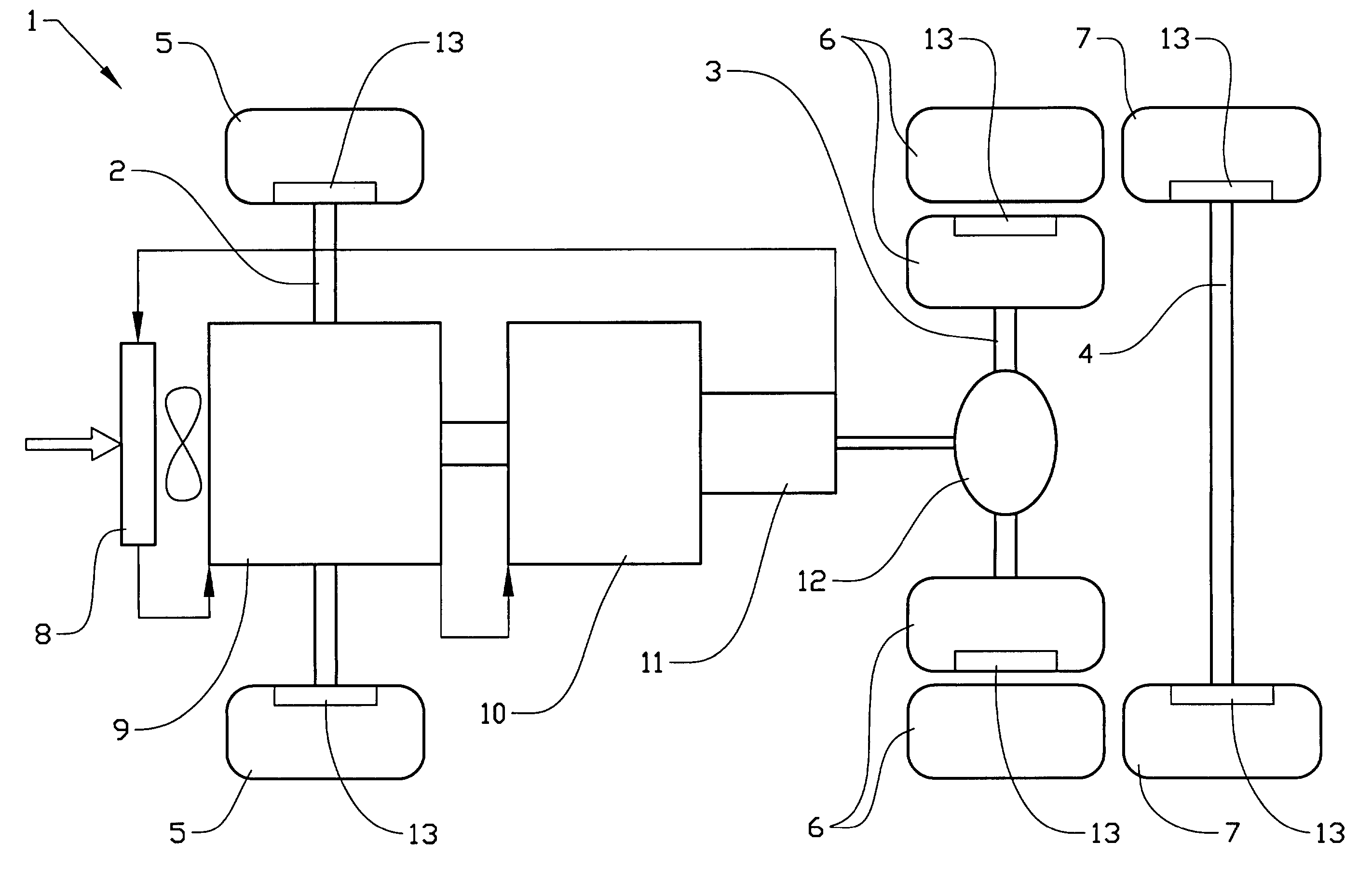
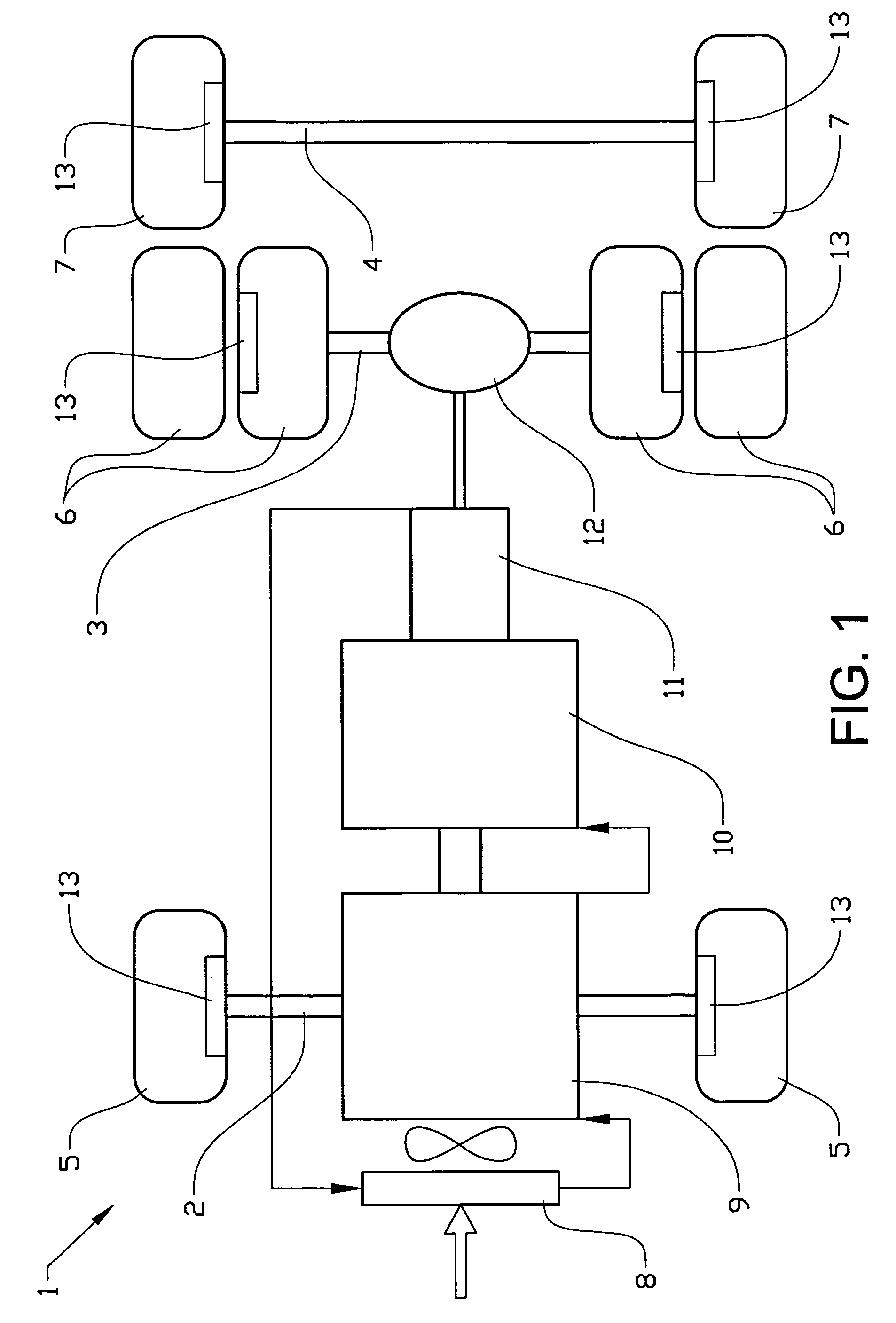
[0032]FIG. 1 diagrammatically shows a vehicle 1 with a front wheel axle 2, a first rear wheel axle 3 and a second rear wheel axle 4. Mounted on the front wheel axle 2 is a front wheel pair 5 which steers the vehicle. A first rear wheel pair 6 is mounted on the first rear wheel axle 3 which is also the driving axle of the vehicle.

[0033] The first rear wheel pair 6 consi...


PUM


Abstract

Method and apparatus for distributing brake torque between at least a first and a second braking device on a motor vehicle having at least two wheel pairs. The first braking device is a friction brake which acts on at least one wheel pair and the second braking device acts on at least one driven wheel pair. The distribution of brake torque between the first braking device and the second braking device takes account of brake torque required and also the maximum brake torque the first braking device and the second braking device can deliver. The distribution of brake torque takes place when the vehicle is driven with a cruise control function.

Description

CROSS-REFERENCE TO RELATED APPLICATIONS [0001] The present application is a continuation patent application of International Application No. PCT / SE2003 / 001764 filed 13 Nov. 2003 which was published in English pursuant to Article 21(2) of the Patent Cooperation Treaty, and which claims priority to Swedish Application No. 0203498-1 filed 26 Nov. 2002. Said applications are expressly incorporated herein by reference in their entireties.TECHNICAL FIELD [0002] The present invention relates to a method and apparatus for distributing the brake torque between service brakes and auxiliary brakes in a vehicle when the vehicle is driven with a cruise control function. BACKGROUND OF INVENTION [0003] It is known to arrange auxiliary brakes in a vehicle as a supplement to the service brakes of the vehicle. [0004] Auxiliary brakes are used mainly in heavy-duty vehicles for the primary purpose of sparing the service brakes of the vehicle, especially when driving on long downhill gradients and it is...

Claims


Application Information

Patent Timeline
Patent Type & Authority Applications(United States)
IPC IPC(8): B60T13/74B60T8/00B60T8/24
CPCB60T8/00B60T8/24
Inventor LINGMAN, PETERERIKSSON, ANDERSSABELSTROM, MATSTERBORN, BENGT
Owner VOLVO LASTVAGNAR AB
Why Eureka
Try Eureka