Shoulder ring set on casing hanger trip

a technology of casing hanger and shoulder ring, which is applied in the direction of sealing/packing, mechanical equipment, borehole/well accessories, etc., can solve the problems of high cost and need an extra trip

Inactive Publication Date: 2006-12-19
VETCO GRAY
View PDF18 Cites 27 Cited by
  • Summary
  • Abstract
  • Description
  • Claims
  • Application Information

AI Technical Summary

Problems solved by technology

However, running the load ring on a running tool would require an extra trip from the drilling rig to the sea floor.
In very deep water, the extra trip would be expensive.

Method used


Image

  • Shoulder ring set on casing hanger trip
  • Shoulder ring set on casing hanger trip
  • Shoulder ring set on casing hanger trip

Examples


Embodiment Construction

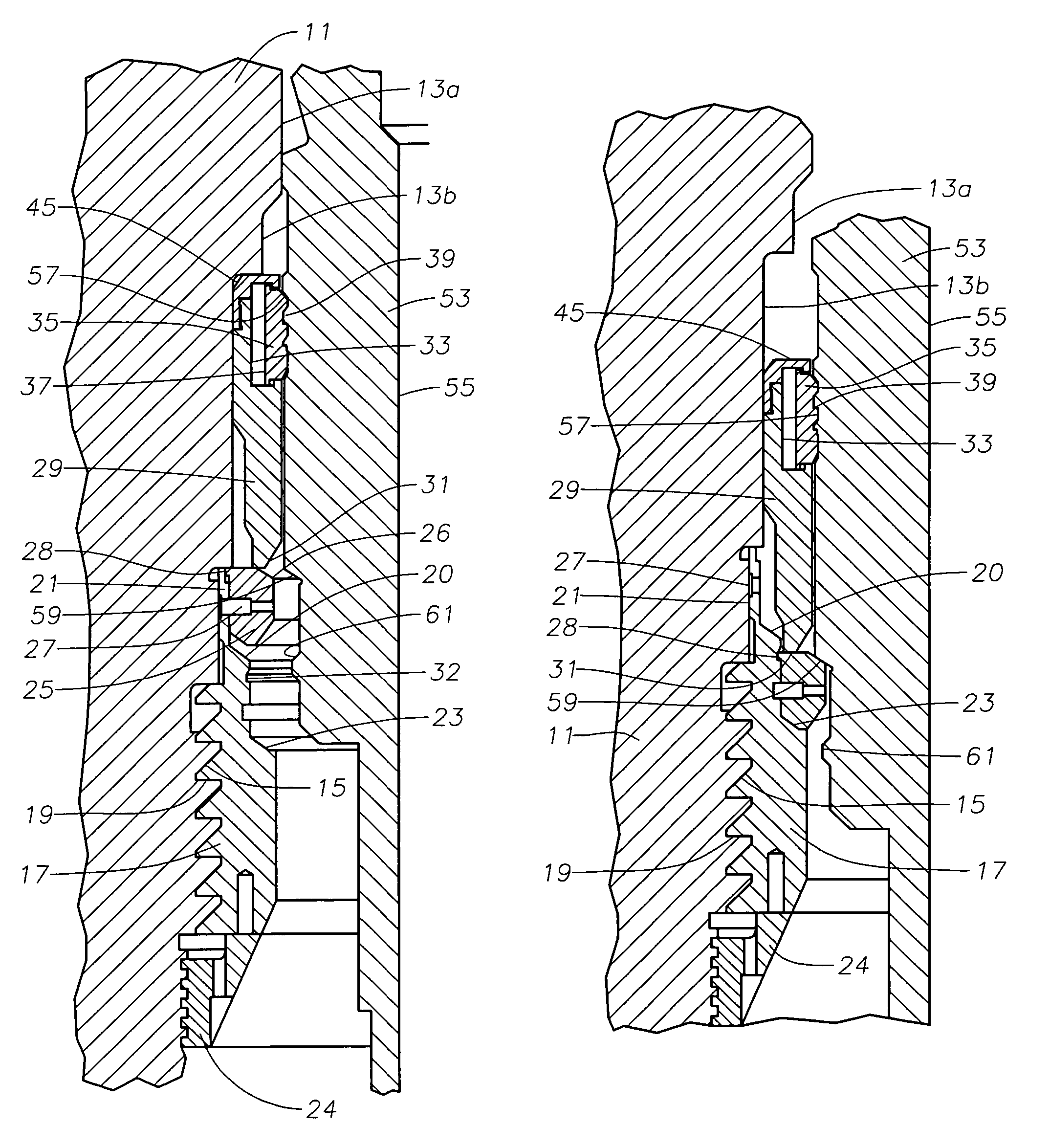
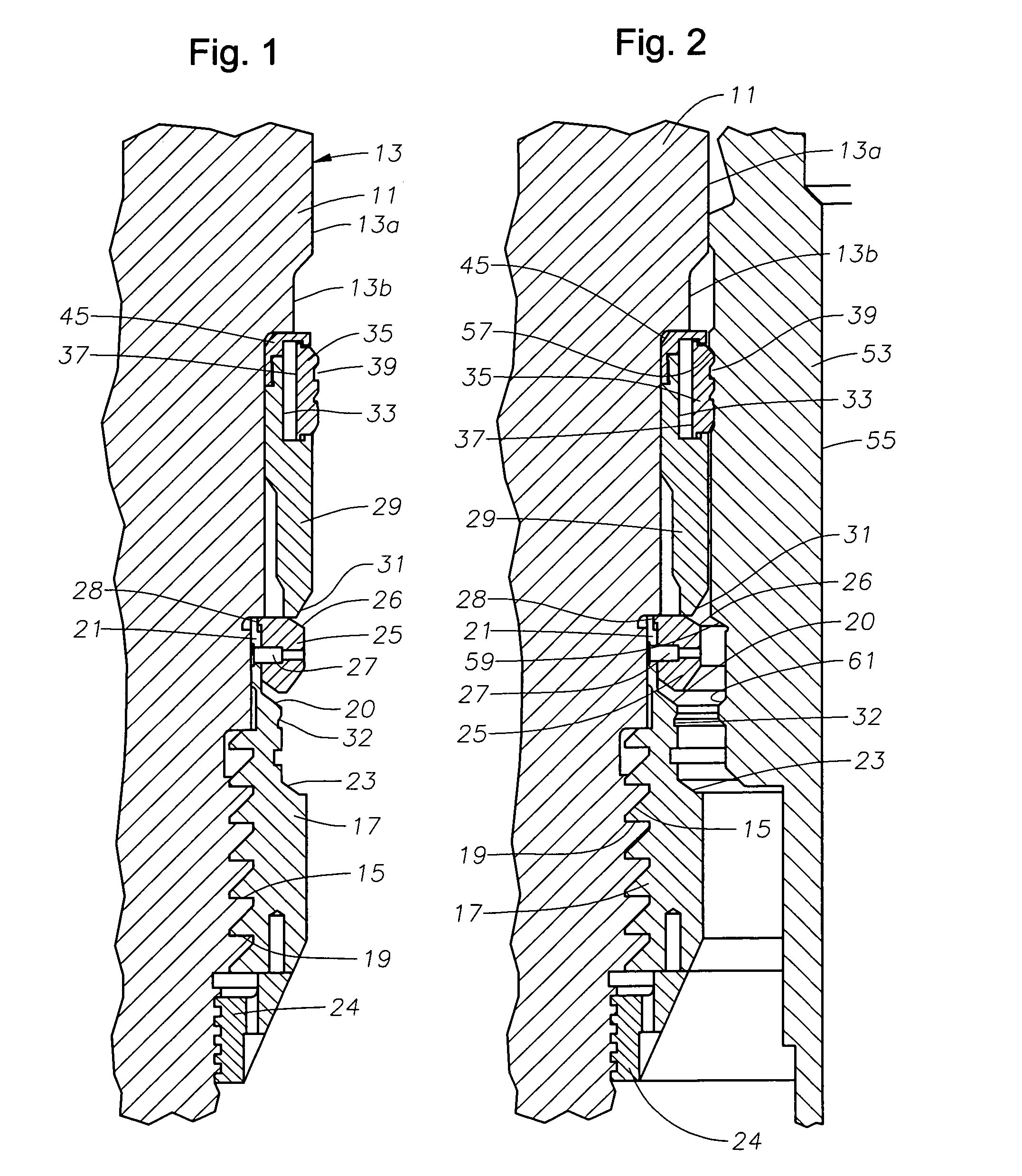
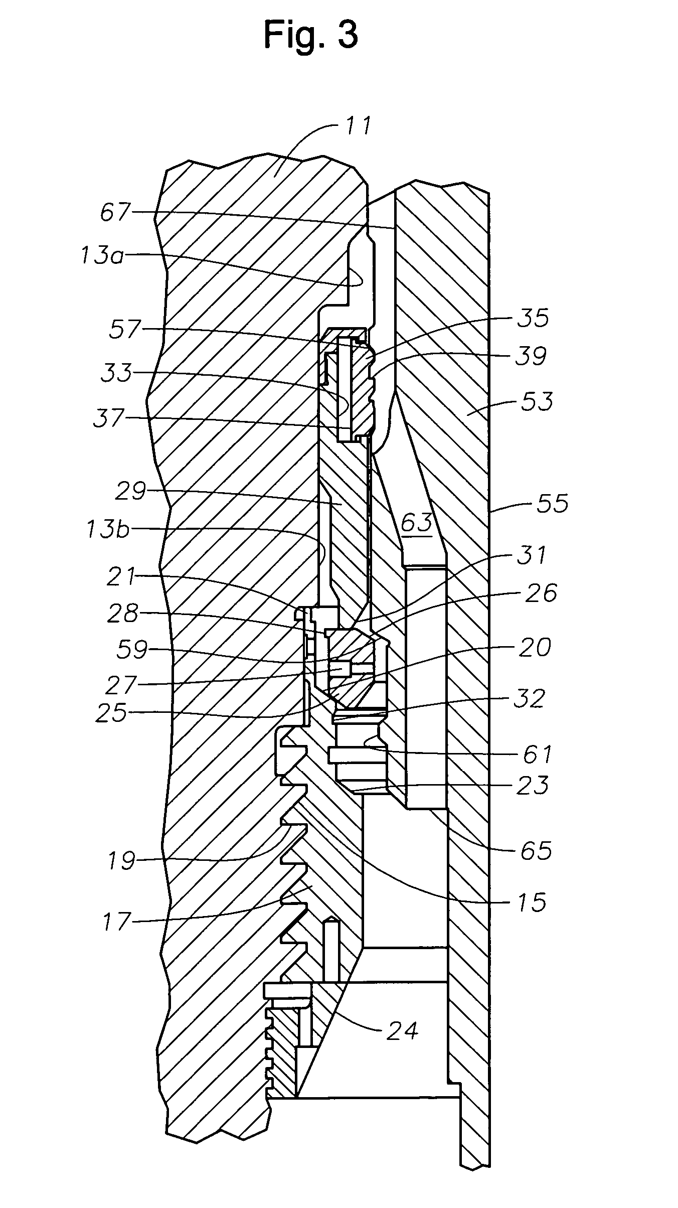
[0013]Referring to FIG. 1, wellhead housing 11 is a large tubular member that is typically located at the upper end of a well in a subsea location near the sea floor. Wellhead housing 11 has a bore 13 extending through it with an internally threaded profile 15. Bore 13 has a minimum inner diameter portion 13a and an enlarged diameter portion or recess 13b extending below.

[0014]A support ring 17 has external threads 19 that secure to threads 15 within wellhead housing bore portion 13b. Support ring 17 is a solid cylindrical member that is stationarily mounted to wellhead housing 11 prior to lowering wellhead housing 11 into the sea. Support ring 17 has an an upward facing support shoulder 23, a ramp 20 above support shoulder 23, and a neck 21 extending upward from ramp 20. Neck 21 has a larger inner diameter than the smallest inner diameter bore portion 13a. A retainer ring 24 secures to a threaded profile formed in bore portion 13b below support ring 17. Retainer ring 24 retains sup...


PUM


Abstract

A wellhead housing has a bore with a support shoulder, a ramp surface extending upward and outward from the support shoulder, and a recess extending upward from the ramp. A split, resilient load ring is carried in an initial position in the recess. A retractable and axially movable latch ring is carried in the recess above the load ring. A casing hanger has a profile that engages the latch ring as the casing hanger moves downwardly in the bore, causing the latch ring to move downward and pushing the load ring to the set position.

Description

CROSS-REFERENCE TO RELATED APPLICATION[0001]This application claimes priority to provisional application 60 / 591,067 filed Jul. 26, 2004.FIELD OF THE INVENTION[0002]This invention relates in general to subsea wellhead assemblies, and in particular to a full bore wellhead housing, wherein the operator sets a casing hanger load shoulder ring during the casing hanger running procedure.BACKGROUND OF THE INVENTION[0003]A typical subsea well has a wellhead housing at the upper end of the well. The wellhead housing is a tubular member having a bore. A string of large diameter casing attaches to the lower end of the wellhead housing and extends into the well. After further drilling through the wellhead housing, a smaller diameter string of casing is installed. A casing hanger at the upper end of the smaller diameter string of casing lands in the bore on a load shoulder.[0004]In one type of wellhead housing, the load shoulder is permanently formed in the bore during manufacturing. This perman...

Claims


Application Information

Patent Timeline
Patent Type & Authority Patents(United States)
IPC IPC(8): E21B29/12
CPCE21B33/043
Inventor FORD, DAVID L.
Owner VETCO GRAY
Why Eureka
Try Eureka