Apparatus for plasticating thermoplastic resin including polypropylene

a thermoplastic resin and plasticizing technology, applied in clay mixing apparatus, rotary stirring mixers, horizontally mounted tools, etc., can solve the problems of reducing the efficiency of viscous shear heating in the melting section, reducing the extrusion rate of polypropylene resin pellets, and reducing the viscosity. , to achieve the effect of low viscosity, low extrusion rate of polypropylene, and low friction

Active Publication Date: 2007-01-02
XALOY INCORPORATED
View PDF43 Cites 23 Cited by
  • Summary
  • Abstract
  • Description
  • Claims
  • Application Information

AI Technical Summary

Benefits of technology

[0010]It has been demonstrated that pressure within the barrel and along its length rises sooner and remains at a higher magnitude when plasticating polypropylene with the apparatus of this invention as compared to the resulting pressure profile produced when plasticating polypropylene with conventional apparatus. These data confirm the improved heating rate and flow rate of polypropylene through plasticating apparatus according to this invention.

Problems solved by technology

Its low melt viscosity reduces the effectiveness of viscous shear heating in the melting section; therefore, its rate of melting is lower than that of polymers having a higher melt viscosity.
High stiffness or rigidity makes it more difficult for polypropylene resin pellets to be compressed and transported in the feed and compression sections of a plasticating screw.
At best these conflicting design choices merely compensate for the physical and chemical properties of polypropylene that diminish its output rate, and they potentially impose higher equipment costs and increase energy costs.

Method used


Image

  • Apparatus for plasticating thermoplastic resin including polypropylene
  • Apparatus for plasticating thermoplastic resin including polypropylene
  • Apparatus for plasticating thermoplastic resin including polypropylene

Examples


Embodiment Construction

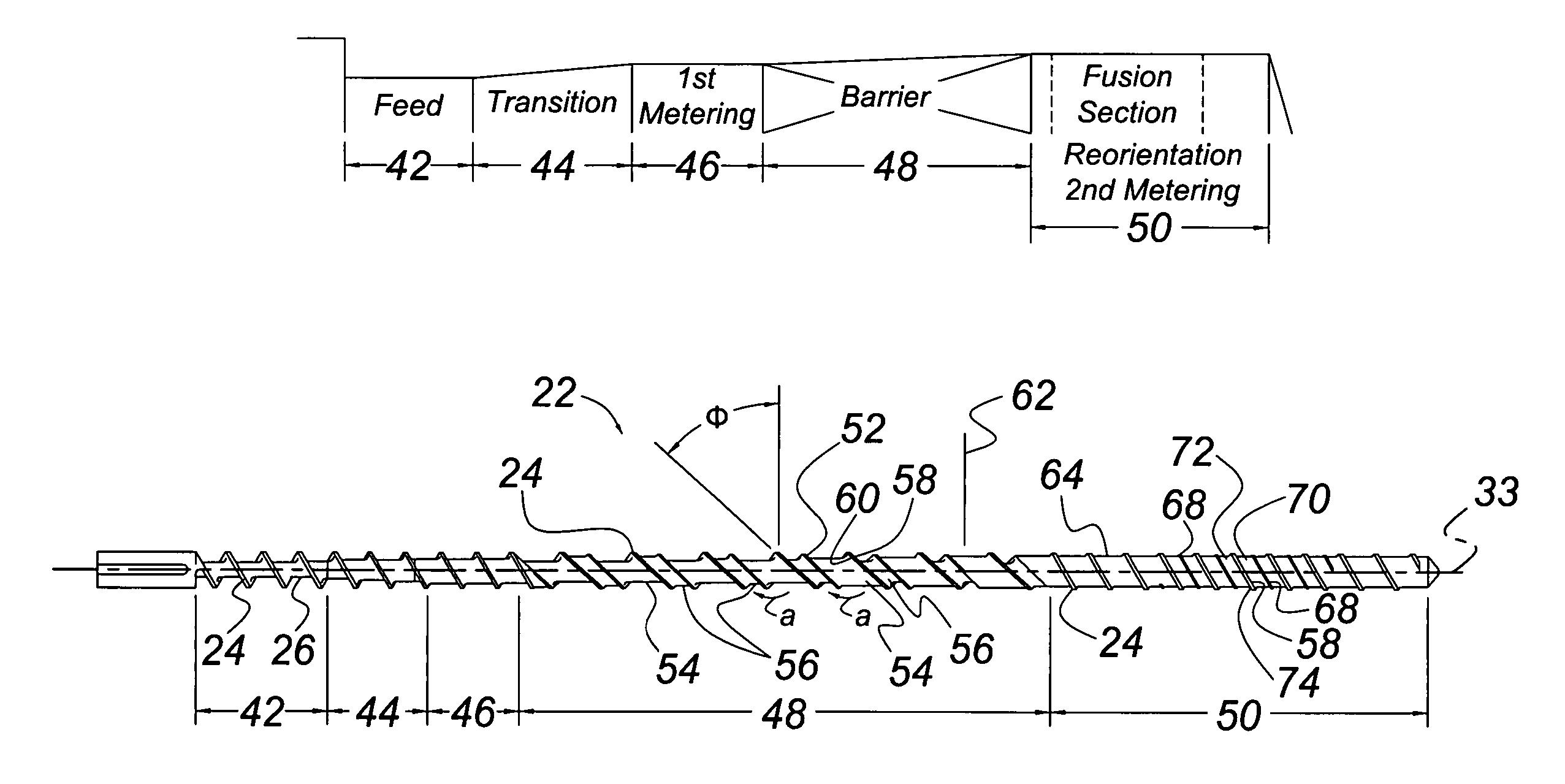
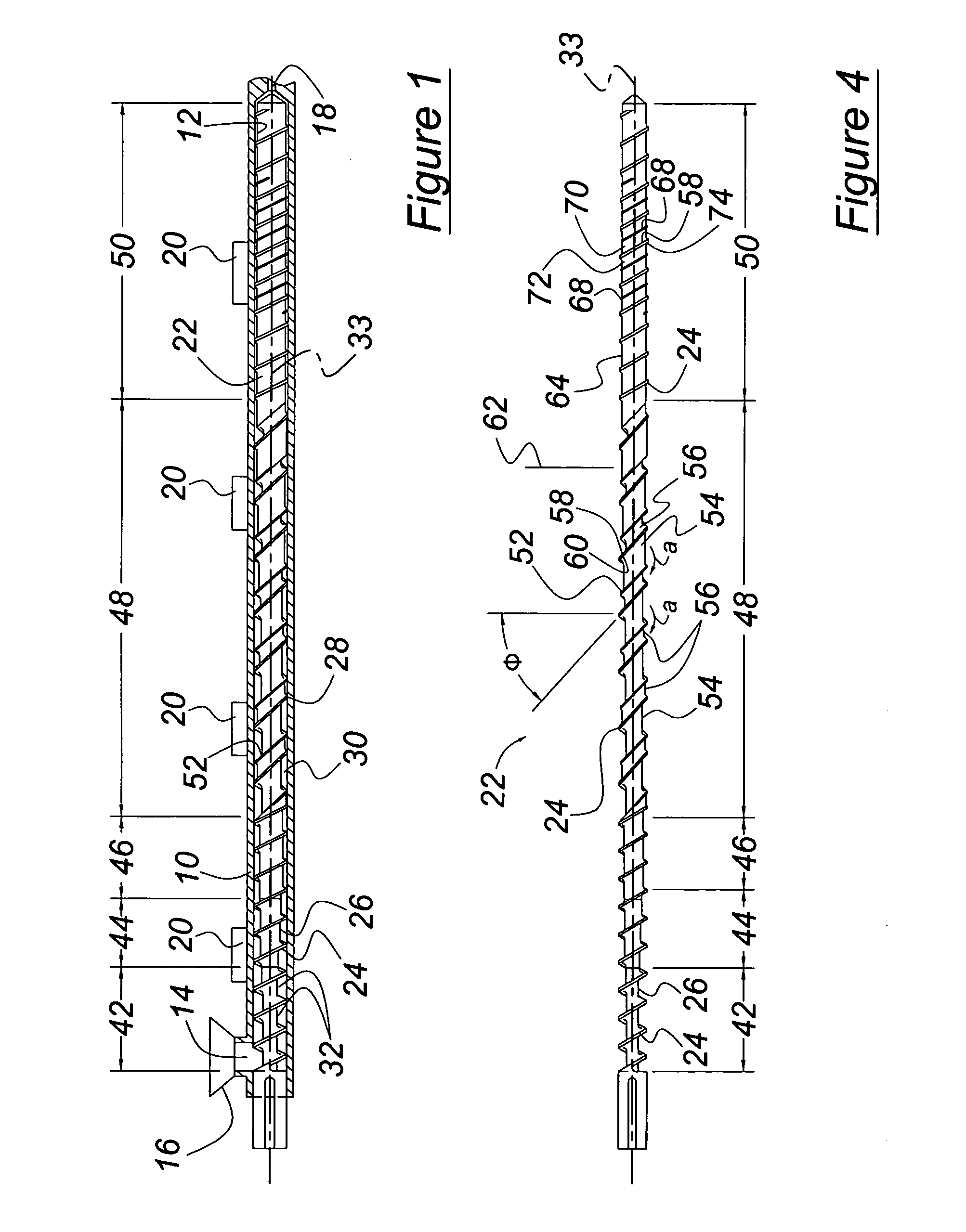
[0022]Referring first to FIG. 1, the plasticating apparatus for processing granules or pellets of resin includes a cylindrical barrel 10 having an inner surface 12. The barrel 10 is provided with an inlet port 14 for the admission, via a feed hopper 16, of one or more solid particulate resinous materials and any required additives or agents. The barrel 10 is also provided with a discharge or outlet port 18 for the discharge of plasticated molten extrudate to a mold or die (not shown) or other exit configuration. Elements 20 for heating and cooling the barrel can be provided at the outer surface of the barrel 10. There may also be a vent in the barrel wall through which undesirable volatilized matter in the resin leaves the barrel, and another inlet through which material, such as a dye is added to the contents of the barrel.

[0023]Located in the barrel 10 is a screw 22, supported for rotation and extending axially from the inlet port 14 to the outlet port 18. The screw 22 includes a ...


PUM

PropertyMeasurementUnit
radiusaaaaaaaaaa
radiusaaaaaaaaaa
diameteraaaaaaaaaa

Abstract

Apparatus according to this invention for plasticating a resin polymer, especially polypropylene, includes a barrel having an inlet, outlet, and inner surface. A screw, located within and closely spaced from the inner surface of the barrel, has a longitudinal axis extending from the inlet toward the outlet, and includes length sections arranged in a series along the axis. The screw includes a core and a main flight located on and projecting radially from the core, extending in a helix along the axis, and having a push side and a trailing side. The screw sections include a feed section, a transition section following the feed section, a metering section following the transition section, and a barrier melting section following the metering section.

Description

BACKGROUND OF THE INVENTION[0001]This invention relates to plasticating resin using a screw rotating in an extrusion or injection molding barrel, from which the resin extrudes or flows to form a product in a die or mold. More particularly, the invention pertains to the arrangement and structural form of various sections of a screw that is especially suited for use in plasticating polypropylene resin.[0002]Polypropylene has been commercially available since 1957 and has remained the fastest growing major thermoplastic, its growth rate being greater than that of many other commodity polymers. The resin is readily available at relatively low cost, and it possesses many unique properties that are suitable for a wide variety of consumer and industrial products. Its excellent crack resistance, low creep rate, low density and high melting point have contributed to its broad applications in injection molding, film, fiber and filaments.[0003]Its fabrication, however, requires an extrusion st...

Claims


Application Information

Patent Timeline
Patent Type & Authority Patents(United States)
IPC IPC(8): B29B7/42B29C48/65B29C48/05B29C48/08B29C48/53
CPCB29C47/6018B29C47/625B29C47/60B29C47/0014B29C47/0021B29K2023/12B29C48/05B29C48/08B29C48/53B29C48/65B29B7/429
Inventor WOMER, TIMOTHY W.SMITH, WALTER S.
Owner XALOY INCORPORATED
Why Eureka
Try Eureka