Inflatable boat with a high pressure inflatable keel

a high-pressure inflatable, inflatable boat technology, applied in the field of inflatable boats, can solve the problems of insignificant drawbacks of inflatable floor, inflatable keel-forming spacers, and more serious problems of inflatable floors, and achieve the effect of convenient installation

Active Publication Date: 2007-01-09
ZODIAC MILPRO INT
View PDF9 Cites 8 Cited by
  • Summary
  • Abstract
  • Description
  • Claims
  • Application Information

AI Technical Summary

Benefits of technology

[0007]Essentially, the object of the invention is to propose an original and inexpensive solution for solving the problem posed, without that also resulting in a significant modification to the general structure of the boat.

Problems solved by technology

Unfortunately, such inflatable keel-forming spacers suffer from a drawback that lies in the narrowness of the zone in which they are in contact with the floor.
If the floor is insufficiently rigid, it can, over time, end up curving significantly in its central longitudinal region.
Such a drawback might remain relatively insignificant with a floor made of wood or of a lightweight metal, regardless of whether it is made up of juxtaposed slats or of juxtaposed panels.
However, the problem can arise more significantly with inflatable floors, i.e. floors formed by a flat chamber braced internally by ties and inflated under a relative high pressure.

Method used


Image

  • Inflatable boat with a high pressure inflatable keel
  • Inflatable boat with a high pressure inflatable keel
  • Inflatable boat with a high pressure inflatable keel

Examples


Embodiment Construction

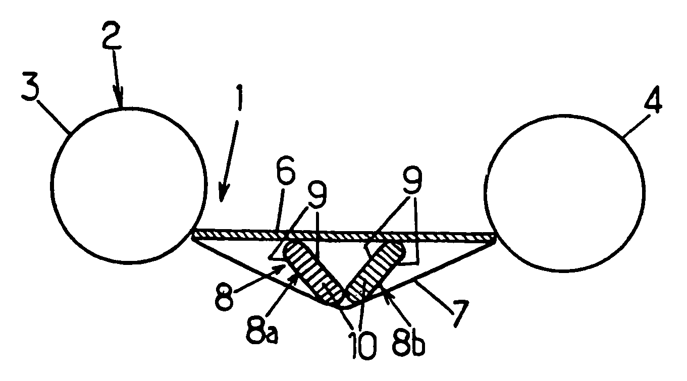
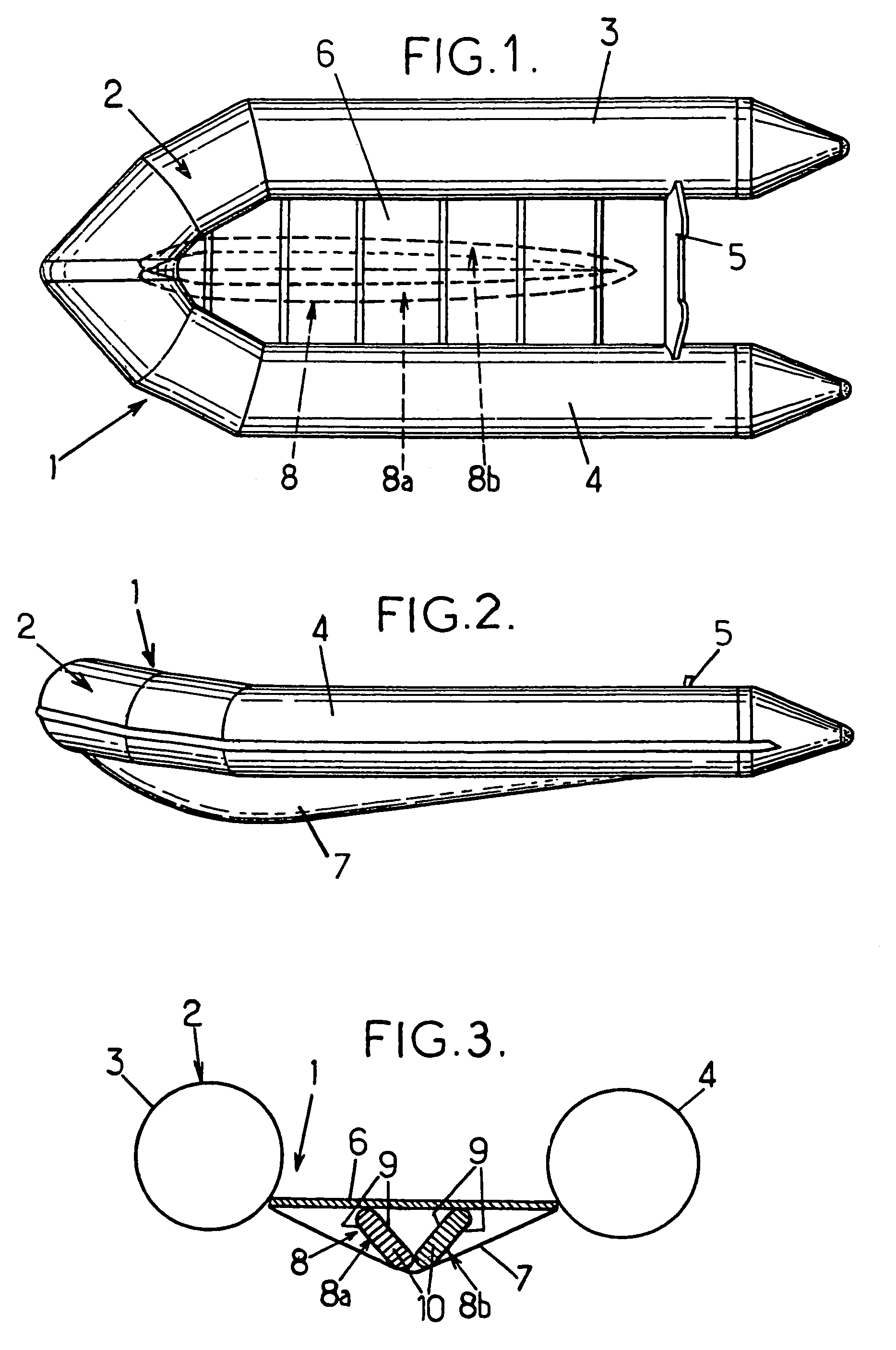
[0028]With reference firstly to FIGS. 1 to 3, the inflatable boat, designated by overall numerical reference 1, comprises a float 2 that is generally U-shaped, that is open at the stern, and that is constituted by a least one pneumatically inflatable tube whose branches 3 and 4 are substantially parallel. Said branches are, at their aft ends, braced by a transom 5.

[0029]Inside the space defined by the U-shaped float 2 and by the transom 5, there extends a floor 6 that is fastened to the float and to the transom, and that is rigid, at least transversely.

[0030]In the example shown in FIGS. 1 to 3, the rigid floor is made up of slats or panels extending transversely to the branches 3, 4 of the tube, said slats or panels, in particular made of wood or of metal, being hinged together.

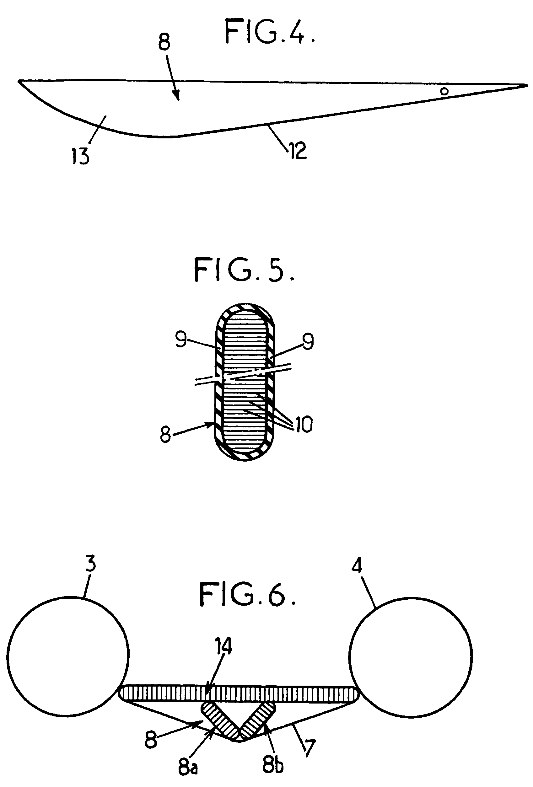
[0031]Finally a bottom sheet constituting a V-shaped keel is formed of a flexible canvas sheet that is fastened to the float 2 and to the transom 5 and that is tensioned by an elongate inflatable keel-formin...


PUM


Abstract

An inflatable boat comprising: an inflatable float that is U-shaped and open at the stern, and that braced by a transom; a floor that is disposed inside the space defined by the float, and a V-shaped keel formed of a flexible canvas sheet fastened to the float and to the transom and tensioned by a longitudinal inflatable keel-forming spacer interposed between the floor and the canvas sheet;the inflatable keel-forming spacer is formed by at least two elongate and flat chambers inflated under a relatively high pressure; and the two chambers have their respective bottom longitudinal edges touching and their respective top longitudinal edges spaced apart from each other so that the keel-forming spacer is generally V-shaped in cross-section.

Description

CROSS REFERENCE TO RELATED APPLICATION[0001]This application claims priority to French Patent Application No. 04 06372 filed on Jun. 11, 2004, the contents of which are incorporated by reference herein.FIELD OF THE INVENTION[0002]The present invention relates generally to the field of inflatable boats, and it relates more specifically to improvements made to inflatable boats of the type comprising: a float that is generally U-shaped and open at the stern, and that is made up of at least one pneumatically inflatable tube whose aft ends are braced by a transom; a floor that is rigid at least transversely and that is disposed inside the space defined by the float, and a V-shaped keel formed of a flexible canvas sheet fastened to the float and to the transom and tensioned by a longitudinal inflatable keel-forming spacer interposed between said floor and said canvas sheet.BACKGROUND OF THE INVENTION[0003]Boats arranged in this way are already known, in particular from documents FR 1 155 ...

Claims


Application Information

Patent Timeline
Patent Type & Authority Patents(United States)
IPC IPC(8): B63B7/00B63B35/58B63B3/38B63B7/08
CPCB63B7/082B63B7/08
Inventor DURAND, MANUELBOUDEAU, LIONEL
Owner ZODIAC MILPRO INT
Why Eureka
Try Eureka