
Merchandise output device of a vending machine

a vending machine and output device technology, applied in the field of vending machines, can solve the problem that the vending machine b>40/b> cannot be sold successfully, and achieve the effect of improving the prior art defects

Inactive Publication Date: 2007-02-13
YAO SHEN HAO
View PDF16 Cites 26 Cited by
  • Summary
  • Abstract
  • Description
  • Claims
  • Application Information

AI Technical Summary

Benefits of technology

"The present invention provides a merchandise output device for a vending machine that improves upon previous designs. The device includes a machine body, a groove body, a rotary disk, and a guide plate. The groove body is in the machine body and the rotary disk is installed in the groove body. The bottom of the groove body has an outlet for outputting merchandise, which is connected to a transfer tube at the bottom of the machine body. The rotary disk has multiple receiving holes for receiving merchandises and is rotatable in the groove body by a motor. The guide plate is installed above the rotary disk and is an approximate right-angled triangular plate. The guide plate is obliquely installed above the rotary disk and is connected to the walls of the groove body. The technical effects of this invention include improved merchandise output, reduced likelihood of merchandise damage, and improved customer experience."

Problems solved by technology

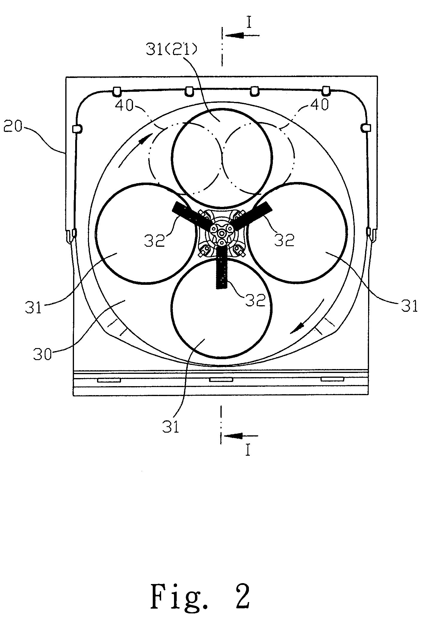
Firstly, before sailing, the merchandises 40 are irregularly placed above the rotary disk 30. Thereby, it is possible that the merchandises 40 are arranged at two sides of the receiving holes 31 of the rotary disk 30, see FIG. 2 so that the merchandises 40 can not successfully drop down. As a result, the merchandises 40 cannot be sold successfully.

Method used


Image

  • Merchandise output device of a vending machine
  • Merchandise output device of a vending machine
  • Merchandise output device of a vending machine

Examples


Embodiment Construction

[0023]In order that those skilled in the art can further understand the present invention, a description will be described in the following in details. However, these descriptions and the appended drawings are only used to cause those skilled in the art to understand the objects, features, and characteristics of the present invention, but not to be used to confine the scope and spirit of the present invention defined in the appended claims.

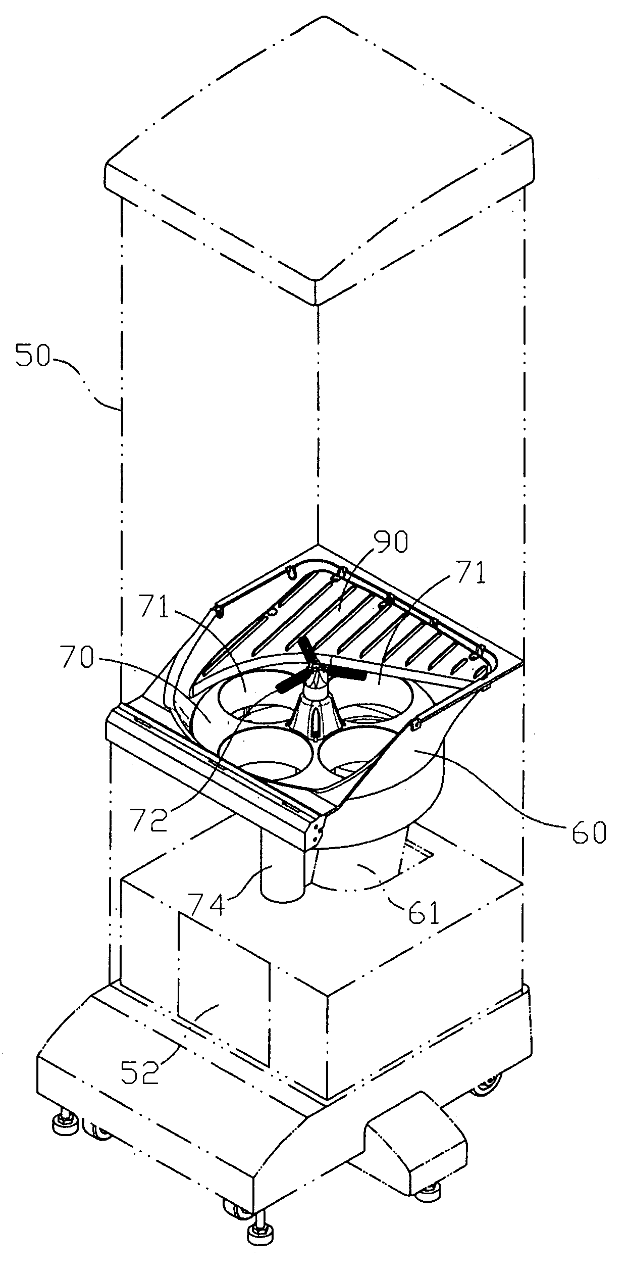
[0024]Referring to FIGS. 5 to 8, the preferred embodiment of the present invention is illustrated.

[0025]See FIG. 5, the present invention has the following elements.

[0026]A machine body 50 is included.

[0027]A groove body 60 is in the machine body 50, see FIGS. 6 and 7. A rotary disk 70 is installed in the groove body 60. A bottom of the groove body 60 has an outlet 61 for outputting a merchandise 80. An inner diameter of the outlet 61 is slightly larger than an outer diameter of the merchandise 80. A lower side of the outlet 61 is connected to a t...


PUM


Abstract

A merchandise output device of a vending machine comprises a machine body; a groove body in the machine body; a rotary disk and a rotary disk and a guide plate installed above the rotary disk and being an approximate right-angled triangular plate. The guide plate is obliquely installed above the rotary disk corresponding to the upper side of the outlet at the bottom of the groove body. A first right angle side of the guide plate is obliquely installed to a first wall of the groove body. A first apex between the first right angle side and the hypotenuse is placed near an upper side of the rotary disk. The second right angle side is horizontally installed to a second wall of the groove body adjacent to the first wall. A second apex between the second right angle side and the hypotenuse is placed higher than the first apex.

Description

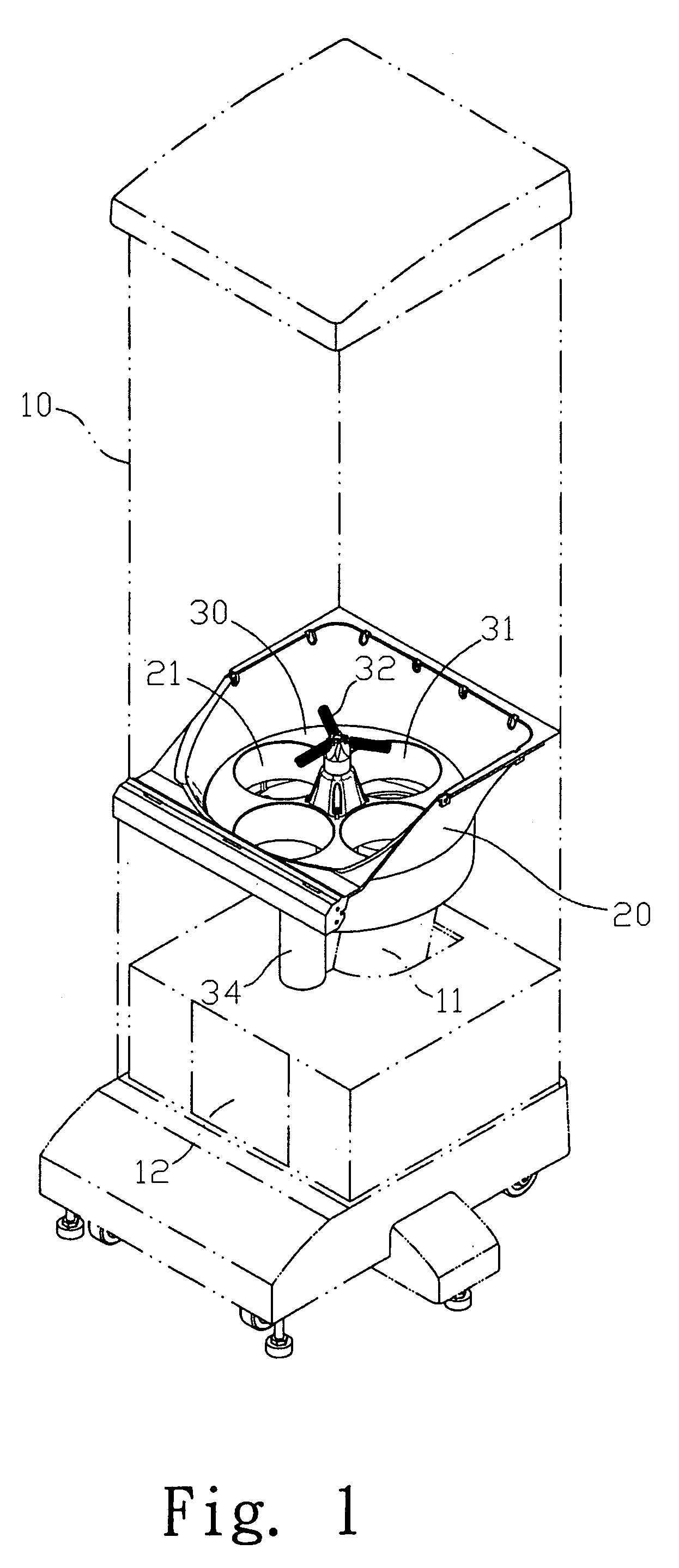
FIELD OF THE INVENTION[0001]The present invention relates to vending machine, and more particular to a merchandise output device of a vending machine, which can improve the prior art defects.BACKGROUND OF THE INVENTION[0002]Referring to FIGS. 1 to 4, a prior art vending machine is illustrated for sailing merchandises of small sizes and having irregular shapes. To output the merchandise successfully, in general, the merchandises in the vending machine have a ball-like shape.[0003]With reference to FIG. 1, the prior art vending machine is illustrated. The vending machine has the following elements. A machine body 10 is included. A groove body 20 is in the machine body 10. A rotary disk 30 is installed in the groove body 20. A bottom of the groove body 20, see FIGS. 2 and 3, has an outlet 21 for outputting a merchandise 40. An inner diameter of the outlet 21 is slightly larger than an outer diameter of the merchandise 40. A lower side of the outlet 21 is connected to a transfer tube 11...

Claims


Application Information

Patent Timeline
Patent Type & Authority Patents(United States)
IPC IPC(8): G07F11/16B65H3/60B65H3/00G07F11/24G07F11/44
CPCG07F11/44G07F11/24
Inventor YAO, SHEN-HAO
Owner YAO SHEN HAO
Learn More