Controller for a quick disconnect slide assembly

a controller and quick disconnect technology, applied in the field of quick disconnect slide assemblies, can solve the problems of further rearward movement of the inner slide segment, prove difficult, and interfere with the bearing assembly, etc., to facilitate sliding movement, facilitate sliding movement, and facilitate sliding movemen

Inactive Publication Date: 2007-02-20
JUDGE RONALD J +2
View PDF20 Cites 27 Cited by
  • Summary
  • Abstract
  • Description
  • Claims
  • Application Information

AI Technical Summary

Problems solved by technology

This often proves difficult since the computer servers are typically heavy and awkward to handle.
If the inner slide segment is not properly aligned in the channel, the end of the inner slide segment can interfere with the bearing assembly.
This makes further rearward movement of the inner slide segment difficult.
In addition to being inconvenient, damage to the bearing assembly or other components of the slide assembly can result if the inner slide segment is forcibly retracted.
However, while it is generally desirable for the lock to engage when the slide assembly is fully extended, it is generally undesirable and inconvenient for the lock to engage as the inner slide segment and attached computer server are first installed in the server rack.

Method used


Image

  • Controller for a quick disconnect slide assembly
  • Controller for a quick disconnect slide assembly
  • Controller for a quick disconnect slide assembly

Examples


Embodiment Construction

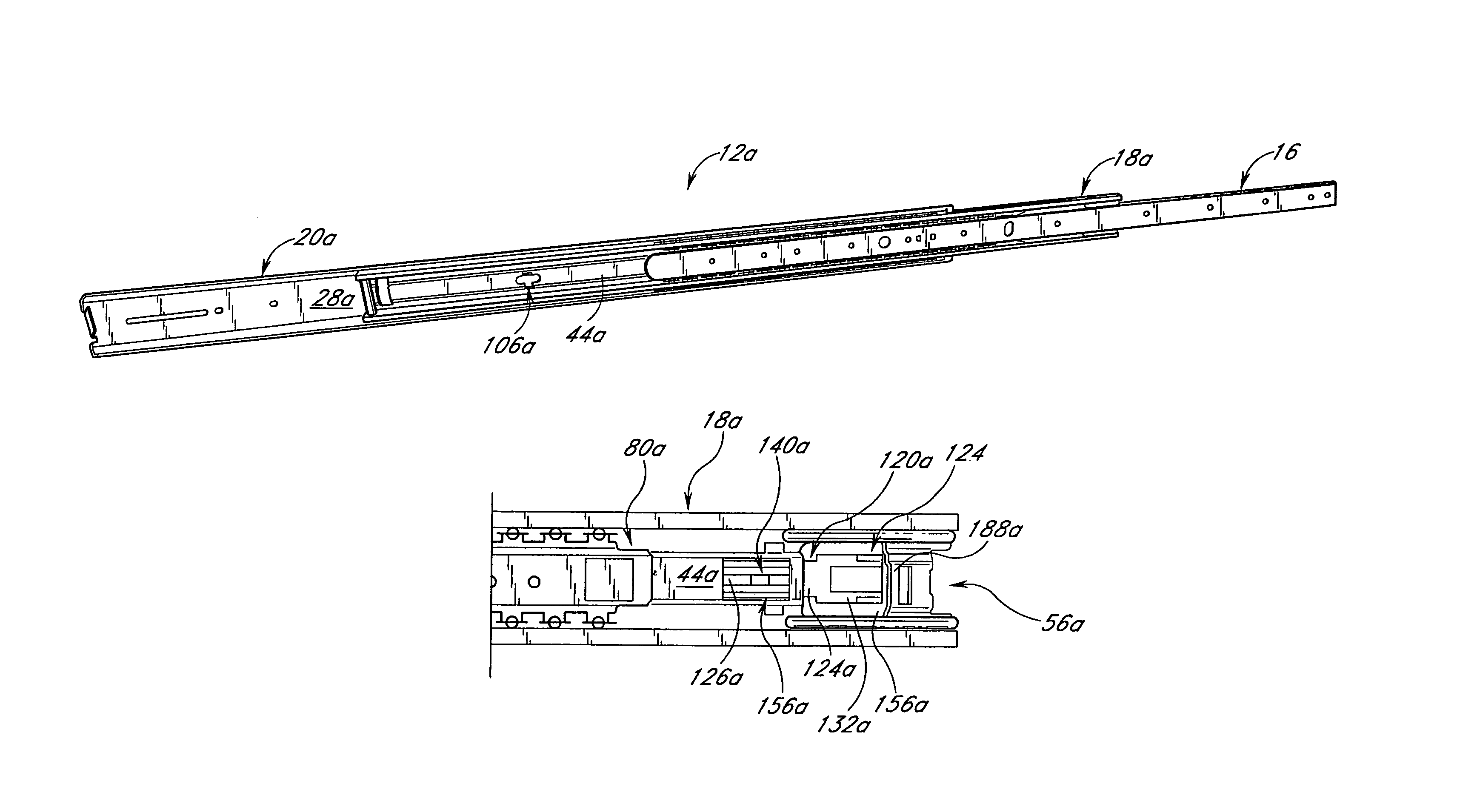
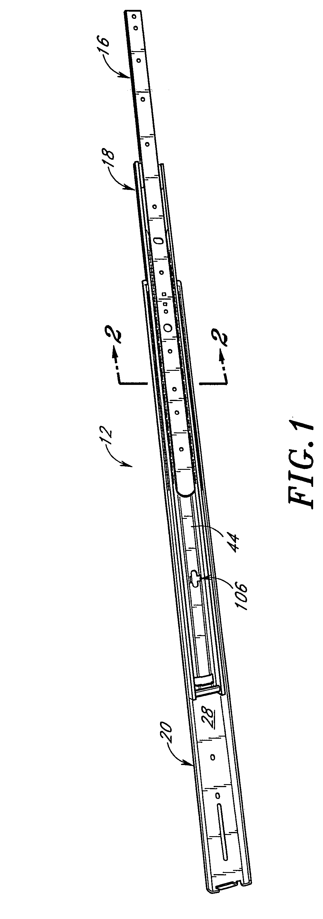
[0037]A slide assembly having features in accordance with the present invention is illustrated in FIG. 1 and designated generally by the reference numeral 12. In the embodiment illustrated in FIG. 1, the slide assembly 12 includes a first or inner slide segment 16, a second or intermediate slide segment 18, and a third or outer slide segment 20. The inner slide segment 16 is adapted for mounting to an outer case or housing of a computer server (not shown). The outer slide segment 20 is adapted for mounting to a stationary server rack structure (not shown). Each computer server desirably is supported in the server rack structure by a pair of slide assemblies 12, one on either side of the computer server, to allow the computer server to slide in and out of the server rack structure.

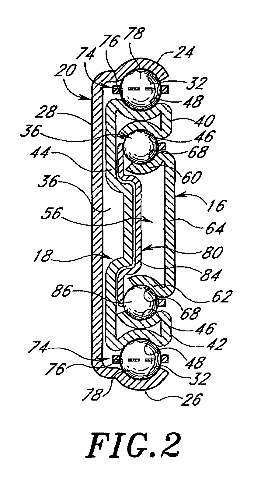
[0038]FIG. 2 is a cross-sectional view of the slide assembly 12 of FIG. 1, taken along the line 2—2 of FIG. 1. With reference to FIGS. 1 and 2, the outer slide segment 20 has a generally C-shaped cross-sect...


PUM


Abstract

A slide assembly includes an inner slide segment, an intermediate slide segment, and an outer slide segment. A bearing assembly is provided between the inner slide segment and the intermediate slide segment. Preferably, a lock arm extends from the outer slide segment and is engageable with an engagement surface of the intermediate slide segment to limit movement of the intermediate slide segment with respect to the outer slide segment. A latch is associated with the intermediate slide segment and comprises a locking portion. The locking portion is selectively engageable with the bearing assembly to limit movement of the bearing assembly.

Description

RELATED APPLICATIONS[0001]This application is a continuation of U.S. patent application Ser. No. 10 / 704,177, filed Nov. 7, 2003, now U.S. Pat. No. 6,820,954 which is a continuation of U.S. patent application Ser. No. 10 / 028,030, filed Dec. 19, 2001, now U.S. Pat. No. 6,655,763, which claims priority to U.S. Provisional Application No. 60 / 257,909, filed Dec. 22, 2000.INCORPORATION BY REFERENCE[0002]The entireties of U.S. patent application Ser. Nos. 10 / 704,177, filed Nov. 7, 2003, and U.S. patent application Ser. No. 10 / 028,030, filed Dec. 19, 2001, now U.S. Pat. No. 6,655,763, and U.S. Provisional Application No. 60 / 257,909, filed Dec. 22, 2000, are hereby incorporated by reference herein and made a part of this specification.BACKGROUND OF THE INVENTION[0003]1. Field of the Invention[0004]The present invention relates to slide assemblies and, more particularly, to quick disconnect-type slide assemblies.[0005]2. Description of the Related Art[0006]For convenience and to conserve floo...

Claims


Application Information

Patent Timeline
Patent Type & Authority Patents(United States)
IPC IPC(8): A47B88/04A47B88/493H05K7/14
CPCA47B88/10H05K7/1421A47B2088/0444A47B2210/0032A47B2210/0059A47B2210/0016H05K7/1489A47B2088/4235A47B88/493
Inventor JUDGE, RONALD J.LYONS, ADAM M.ALBA, TED D.
Owner JUDGE RONALD J
Why Eureka
Try Eureka