Air-blowing apparatus of cleaner

a technology of air blowing apparatus and cleaner, which is applied in the direction of cleaning equipment, machines/engines, liquid fuel engines, etc., can solve the problems of serious noise problems, and achieve the effect of reducing noise and not seriously affecting blowing efficiency

Inactive Publication Date: 2007-02-20
LG ELECTRONICS INC
View PDF9 Cites 7 Cited by
  • Summary
  • Abstract
  • Description
  • Claims
  • Application Information

AI Technical Summary

Benefits of technology

[0017]Therefore, the present invention has been made in view of the above problems, and it is an object of the present invention to provide an air-blowing apparatus of a cleaner that is capable of reducing noise generated due to disturbance while minimizing flow loss of air between a fan and a diffuser.
[0034]In the air-blowing apparatus of the cleaner with the above-mentioned construction according to the present invention, at least a portion of the distance between a fan and a diffuser is larger, in the axial direction of the fan, than the other portion of the distance, whereby noise is reduced while blowing efficiency is not seriously affected.

Problems solved by technology

Consequently, a serious problem of noise is caused.

Method used


Image

  • Air-blowing apparatus of cleaner
  • Air-blowing apparatus of cleaner
  • Air-blowing apparatus of cleaner

Examples


Embodiment Construction

[0040]Now, a preferred embodiment of the present invention will be described in detail with reference to the accompanying drawings.

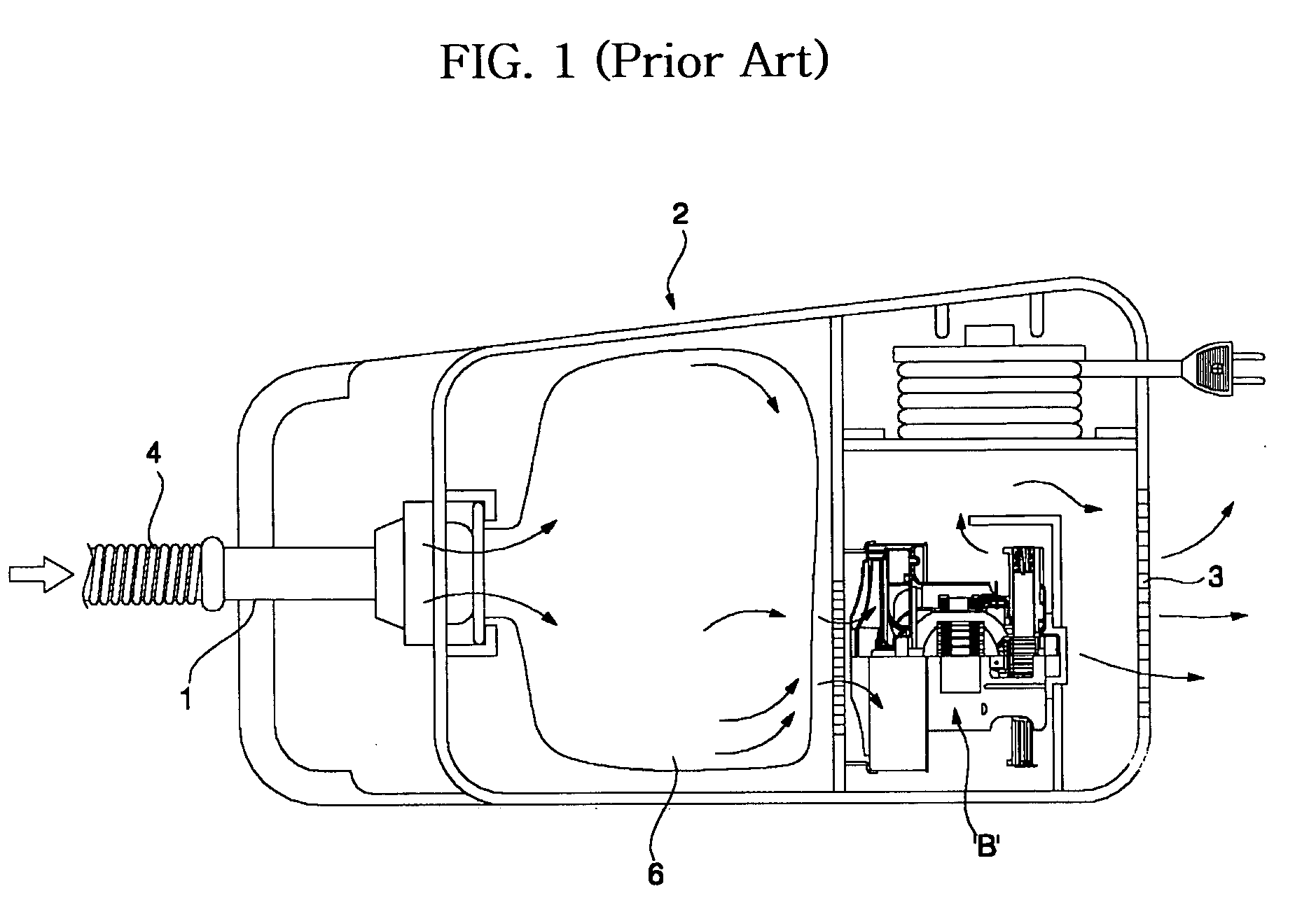
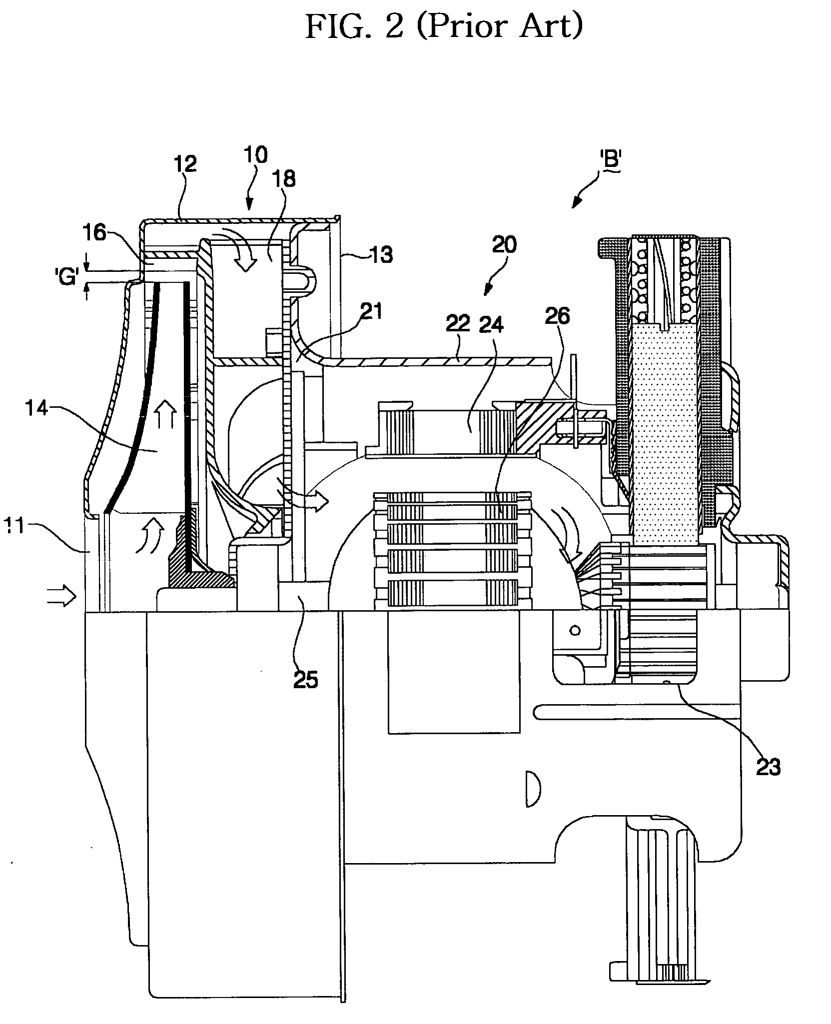
[0041]Although various preferred embodiments of the present invention may be proposed, an air-blowing apparatus of a cleaner according to the most preferred embodiment of the present invention will be described below. The basic construction of the air-blowing apparatus of the cleaner according to the present invention is identical to that of the conventional air-blowing apparatus of the cleaner, the detailed description of which will therefore not be given.

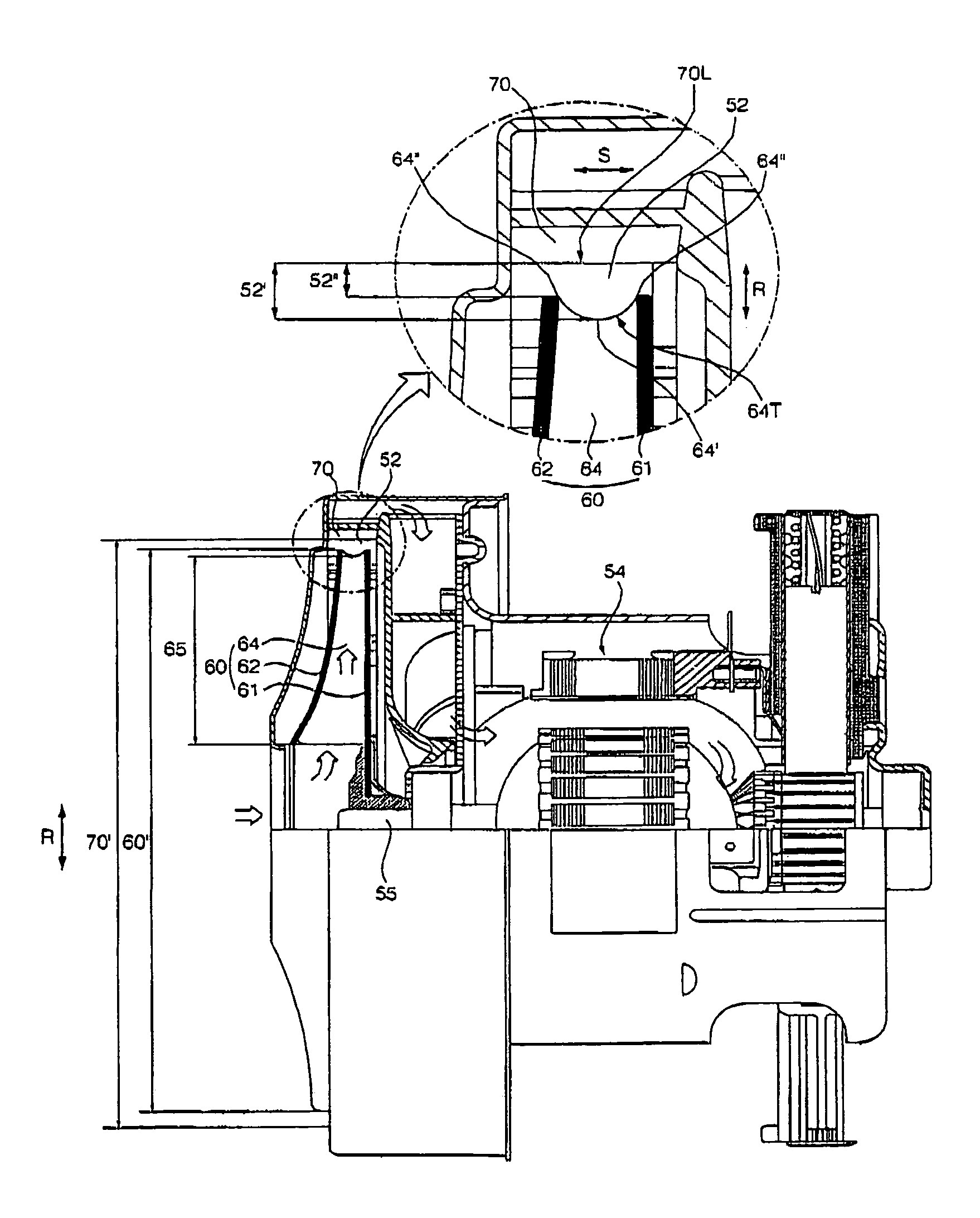
[0042]FIG. 3 is a cross-sectional view, in part, showing an air-blowing apparatus of a cleaner according to a preferred embodiment of the present invention.

[0043]The air-blowing apparatus of the cleaner according to the preferred embodiment of the present invention includes: a fan 60 rotatably mounted in a fan housing 50 for generating a blowing force in the centrifugal direction thereof; and a diffuse...


PUM


Abstract

Disclosed herein is an air-blowing apparatus of a cleaner. The air-blowing apparatus comprises a fan having a plurality of blades spaced apart from each other in the circumferential direction of the fan for generating a blowing force in the centrifugal direction thereof, and a diffuser disposed outside the fan in the radial direction of the fan for diffusing air blown from the fan. Each blade is formed such that at least a part of the blade is shorter than the other part of the blade extending to the outer diameter of the fan, whereby noise is reduced while blowing efficiency is not affected.

Description

BACKGROUND OF THE INVENTION[0001]1. Field of the Invention[0002]The present invention relates to an air-blowing apparatus of a cleaner, and more particularly to an air-blowing apparatus of a cleaner wherein the distance between a fan and a diffuser is partly increased, whereby flow loss is minimized and noise is reduced.[0003]2. Description of the Related Art[0004]FIG. 1 is a view showing the construction of a cleaner with a conventional air-blowing apparatus mounted therein.[0005]Generally, a cleaner comprises: a main body 2; and a suction unit 4 connected to a suction hole 1 formed at the front part of the main body 2 for suctioning waste accumulated on the floor with air. The main body 2 comprises: a dust-collecting compartment 6 for collecting the waste suctioned by means of the suction unit 4, filtering the air, and discharging the filtered air; and an air-blowing apparatus ‘B’ for generating a suction force necessary to introduce the waste into the interior of the main body 2 ...

Claims


Application Information

Patent Timeline
Patent Type & Authority Patents(United States)
IPC IPC(8): F04D29/30A47L9/00A47L5/22F04D29/28F04D29/66
CPCA47L5/22F04D29/666F04D29/30F04D29/282F05D2240/304F05D2250/70A47L9/00
Inventor KIM, WOOKJEON, WAN HOKIM, CHANG JOON
Owner LG ELECTRONICS INC
Why Eureka
Try Eureka