Structure for reducing refrigerant flow loss in compressor

a compressor and flow loss technology, applied in the direction of positive displacement liquid engines, pumping, lighting and heating apparatus, etc., can solve the problems of noise and loss of flow channels, and achieve the effect of reducing the flow loss

Inactive Publication Date: 2005-07-05
LG ELECTRONICS INC
View PDF2 Cites 2 Cited by
  • Summary
  • Abstract
  • Description
  • Claims
  • Application Information

AI Technical Summary

Benefits of technology

[0021]Therefore, an object of the present invention is to provide a structure for reducing a refrigerant flow loss in a compressor that is capable of minimizing a flow loss of a refrigerant gas in its occurrence in the process that a high temperature and high pressure refrigerant gas discharged from a compression mechanism unit flows to a discharge pipe.

Problems solved by technology

Thus, as shown in FIG. 4, in the process that the high temperature and high pressure refrigerant gas discharged from the compression mechanism unit flows to the gap (G) between the stator 2 and the rotor 3, the flowing of the refrigerant gas is not smoothly made and a flowing resistance occurs, resulting in that a flow channel loss and a noise are made.

Method used


Image

  • Structure for reducing refrigerant flow loss in compressor
  • Structure for reducing refrigerant flow loss in compressor
  • Structure for reducing refrigerant flow loss in compressor

Examples


Embodiment Construction

[0035]Reference will now be made in detail to the preferred embodiments of the present invention, examples of which are illustrated in the accompanying drawings.

[0036]FIGS. 5, 6 and 7 show a compressor adopting a refrigerant flow loss reducing structure.

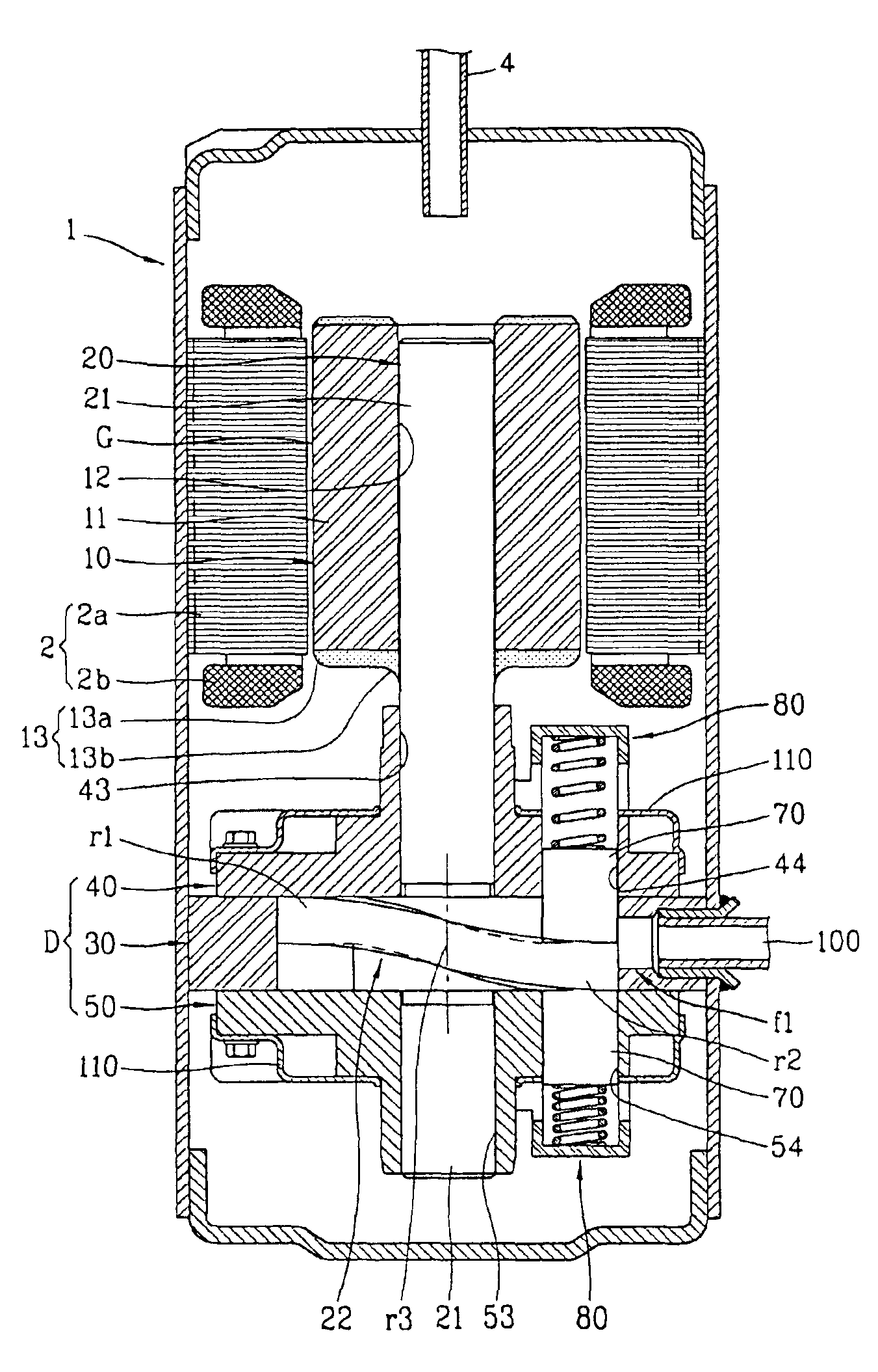
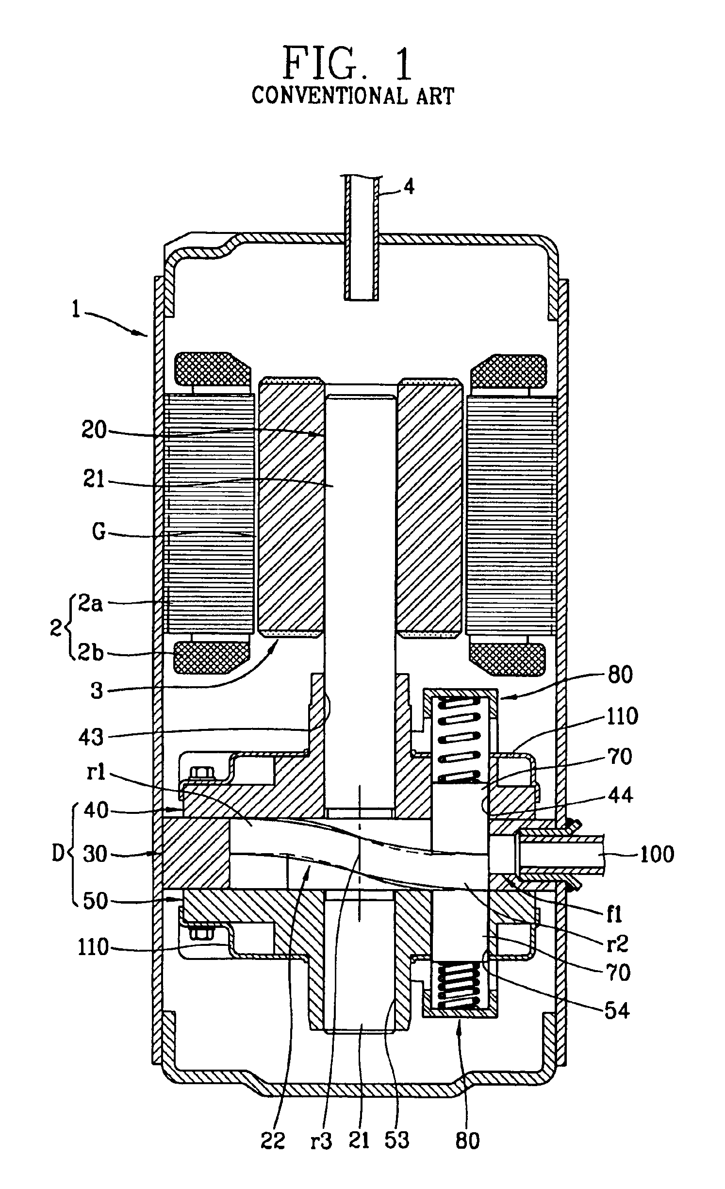
[0037]As shown in FIGS. 5, 6 and 7, a compressor of the present invention includes an electric mechanism unit mounted at one inner side of a hermetic container 1 and generating a driving force and a compression mechanism unit for compressing a refrigerant gas upon receiving the driving force of the electric mechanism unit.

[0038]The electric mechanism unit includes a stator 2 fixedly coupled at one inner side of the hermetic container 1 and a rotor 10 rotatably inserted into the stator 2.

[0039]The stator 2 is formed by winding a winding coil 2b at a stacking body 2a in an annular bar form with a through hole and fixedly coupled at an inner wall of the hermetic container 1.

[0040]A gas passage is formed between the inner wall of the her...


PUM


Abstract

A structure for reducing a refrigerant flow loss in a compressor includes a refrigerant flow resistance reducing unit to reduce a refrigerant channel resistance at a lower surface of a rotor facing a compression mechanism unit. When the high temperature and high pressure refrigerant gas discharged from the compression mechanism unit flows to the discharge pipe through the refrigerant passage including the gap between the rotor and the stator of the electric mechanism unit, the flow resistance of the refrigerant gas is reduced. Therefore, since the refrigerant can flow smoothly, a flow loss of the refrigerant can be reduced and, as a noise generation is reduced, a reliability can be heightened.

Description

TECHNICAL FIELD[0001]The present invention relates to a structure for reducing a refrigerant flow loss of a compressor and, more particularly, to a structure for reducing a flow loss of a compressor that is capable of minimizing a flow loss of a refrigerant gas generated during a process in which a high temperature and high pressure refrigerant gas discharged from a compression mechanism unit flows to a discharge pipe.BACKGROUND ART[0002]In general, a compressor is a device for compressing a fluid, consisting of a hermetic container having an inner space, an electric mechanism unit mounted in the hermetic container and generating a driving force, and a compression mechanism unit compressing a gas upon receiving the driving force.[0003]The compressor is generally classified into a rotary compressor, a reciprocating compressor, a scroll compressor, or the like, according to a type of the compression mechanism unit which compresses a gas.[0004]As shown in FIGS. 1, 2 and 3, the compress...

Claims


Application Information

Patent Timeline
Patent Type & Authority Patents(United States)
IPC IPC(8): F04C23/00F04C18/356F04B39/00
CPCF04C18/3568F04C23/008F04C2240/40F04B39/00
Inventor LEE, CHANG-SOOHONG, SOG-KIE
Owner LG ELECTRONICS INC
Why Eureka
Try Eureka