Collecting chamber and production process

a production process and collection chamber technology, applied in the direction of machines/engines, manufacturing tools, liquid fuel engines, etc., can solve the problems of disproportionately high flow loss still frequently occurring in the surrounding region, large economic disadvantage, and strong dependence on suppliers of cast parts, so as to simplify the pressure connection

Inactive Publication Date: 2012-01-31
SIEMENS AG
View PDF21 Cites 2 Cited by
  • Summary
  • Abstract
  • Description
  • Claims
  • Application Information

AI Technical Summary

Benefits of technology

[0025]owing to the preferably milled transition from the angular collecting chamber to the round pressure connection outlet cross section, which is already present in the collecting chamber itself, the pressure connection is simplified, and this pressure connection can be produced not only as a cast part but instead now also as a turned part (advantage in terms of cost and delivery time), it also being possible for the weld seam preparation for the pressure connection to be carried out by turning on a lathe.
[0026]So that no undesirable nozzle effect occurs at the outlet from the diffuser, an increase in the size of the effective milling cutter diameter is expedient in the manner that the milling cutter, as it is pivoted from the more radial orientation to the more tangential orientation, is guided on a path about a center axis which runs parallel to the milling cutter axis spaced apart therefrom by an eccentricity radius. This can take place in such a manner that the milling cutter axis describes a cylinder with a revolution of the circular motion. Said cylinder may be a straight cylinder. The transitions which are most favorable in terms of flow are established if the eccentricity radius increases as the distance from the second end becomes ever smaller. A continuous increase may be effected in this case, e.g. increasing monotonously depending on the pivoting angle or another parameter which indicates that the distance from the second end is becoming smaller.

Problems solved by technology

Whereas the region of the rotating flow guide contours, for example of the rotor blades or of the impeller, is optimized to the greatest possible extent in terms of flow, disproportionately high flow losses still frequently occur in the surrounding regions.
The size and the non-rotationally symmetrical shape of the collecting chamber mean that the conditions for chip-forming machining of this component are unfavorable, and therefore this component is generally formed as a cast structure.
A structure for material-removing production has nevertheless been provided for those sizes where the solid material is available for such a collecting chamber, since the strong dependence on suppliers for cast parts is a major economic disadvantage.
At the outlet from the collecting chamber into the diffuser, extremely disadvantageous flow losses occur in the case of the milled structure.
The cast component is very complex and results in a costly and unfavorable dependence of the machine manufacturer on the supplier of the cast parts.

Method used


Image

  • Collecting chamber and production process
  • Collecting chamber and production process
  • Collecting chamber and production process

Examples


Embodiment Construction

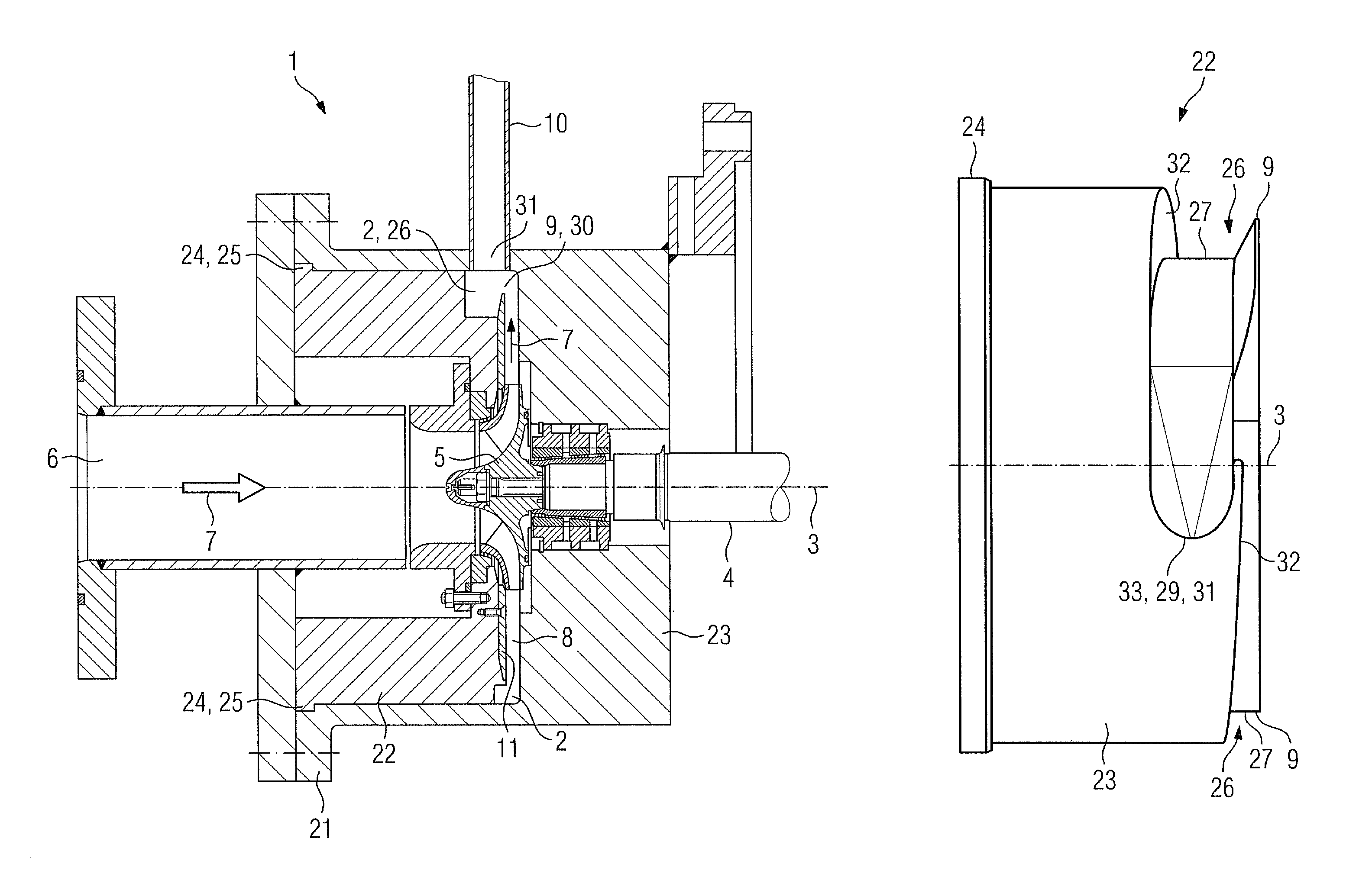
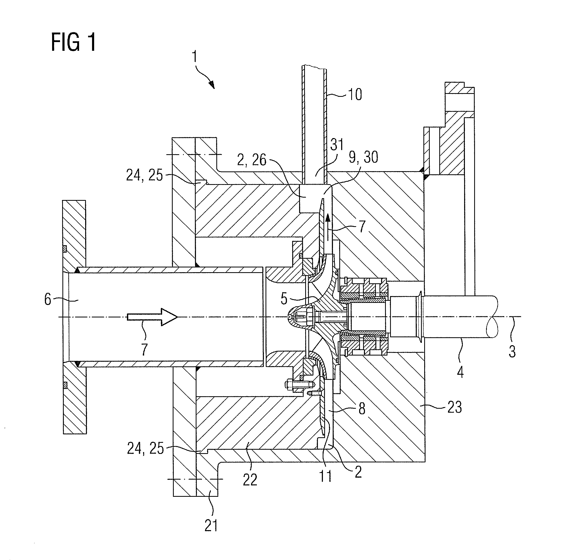
[0035]FIG. 1 shows a longitudinal section through part of a compressor 1 having a collecting chamber 2 according to the invention, which extends about a machine axis 3 in the circumferential direction. The compressor 1 has a rotor 4, and the one end of this rotor which is shown has an impeller 5 (compressor stage of a centrifugal compressor) fitted to it, which forms a free end of the shaft of the rotor 4. A fluid 7 flows axially onto the impeller 5 through an inflow 6, and the impeller conveys the compressed fluid radially outward into an annular chamber 8. After a further 90° deflection 9, the fluid 7 flows from the annular chamber 8 into the collecting chamber 2, where it is collected and passes (in a manner not shown specifically) into a further diffuser 10 (shown offset in the circumferential direction).

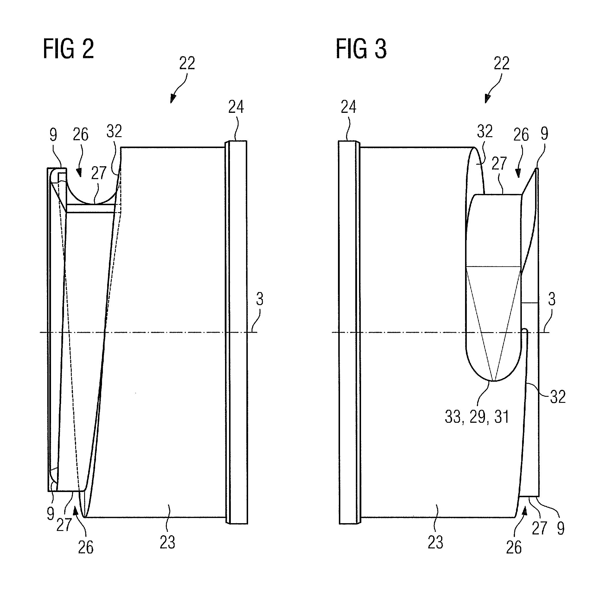
[0036]The collecting chamber 2 is formed by means of an outer shell part 21 and a contour insert 22. The recess in the shell part 21, into which the contour insert 22 is inserte...


PUM

PropertyMeasurementUnit
outlet pressureaaaaaaaaaa
circumferenceaaaaaaaaaa

Abstract

A collecting chamber of a flow machine which expands in the direction of circumference, including at least one outer shell part and a contour insert is provided. The contour insert is provided with a groove which extends in the circumferential direction and is preferably configured as a helical spiral. The contour insert, is cut from a whole unit and is delimited at one end in the circumferential direction by a bent edge so that the flow losses are minimized during the passage from the collecting chamber into a subsequent diffuser.

Description

CROSS REFERENCE TO RELATED APPLICATIONS[0001]This application is the US National Stage of International Application No. PCT / EP2009 / 003299, filed May 8, 2009 and claims the benefit thereof. The International Application claims the benefits of German application No. 10 2008 025 249.2 DE filed May 27, 2008 and international application PCT / EP2009 / 054869 filed Apr. 23, 2009. All of the applications are incorporated by reference herein in their entirety.FIELD OF INVENTION[0002]The invention relates to a collecting chamber of a turbomachine, which widens in the circumferential direction and extends over at least part of the circumference of a machine axis, which collecting chamber is formed from at least one outer shell part and a contour insert, which contour insert has a groove which is milled from solid, extends in the circumferential direction, is laterally delimited at least on one side and has a groove base, which collecting chamber has a first flow opening, which extends in the cir...

Claims


Application Information

Patent Timeline
Patent Type & Authority Patents(United States)
IPC IPC(8): F04D29/42F04D29/44
CPCF04D29/4206F04D29/441Y10T409/305712Y10T409/303808Y10T29/49243Y10T409/30756F04D17/10
Inventor ALBRECHT, HEINRICHJESKE, MICHAELJONEN, WERNERWENTZEL, DANIELWEULE, JAN
Owner SIEMENS AG
Why Eureka
Try Eureka