Method for creating an impeller of a radial turbo fluid energy machine, and stage

a technology of fluid energy machine and impeller, which is applied in the direction of liquid fuel engine components, non-positive displacement fluid engines, pump components, etc., can solve the problems of large pressure loss, less advantageous variable, and local roughness of the surfaces in contact, so as to reduce the surface roughness and increase the surface roughness

Inactive Publication Date: 2017-11-02
SIEMENS AG
View PDF7 Cites 2 Cited by
  • Summary
  • Abstract
  • Description
  • Claims
  • Application Information

AI Technical Summary

Benefits of technology

[0013]The invention also deals with a component created according to the above-defined method. Particular advantage is given here to the impeller of a radial turbo fluid energy machine, in particular a radial turbocompressor.
[0014]One advantageous refinement of the invention provides that the component is created from a one-piece blank. Another advantageous refinement of the invention provides that the component is of one-piece design, wherein advantageously no non-destructively separable parts are provided on the component. Another advantageous refinement of the invention provides that, in one production step, surface regions belonging to a first group of surface regions undergo treatment to reduce the surface roughness. Another advantageous refinement of the invention provides that, in a further production step, surface regions assigned to a second group of surface regions undergo treatment to increase the surface roughness.

Problems solved by technology

However, this variant is less advantageous.
Large pressure losses arise where the local flow velocities and the local roughnesses of the surfaces in contact with the flow are high.

Method used


Image

  • Method for creating an impeller of a radial turbo fluid energy machine, and stage
  • Method for creating an impeller of a radial turbo fluid energy machine, and stage
  • Method for creating an impeller of a radial turbo fluid energy machine, and stage

Examples


Embodiment Construction

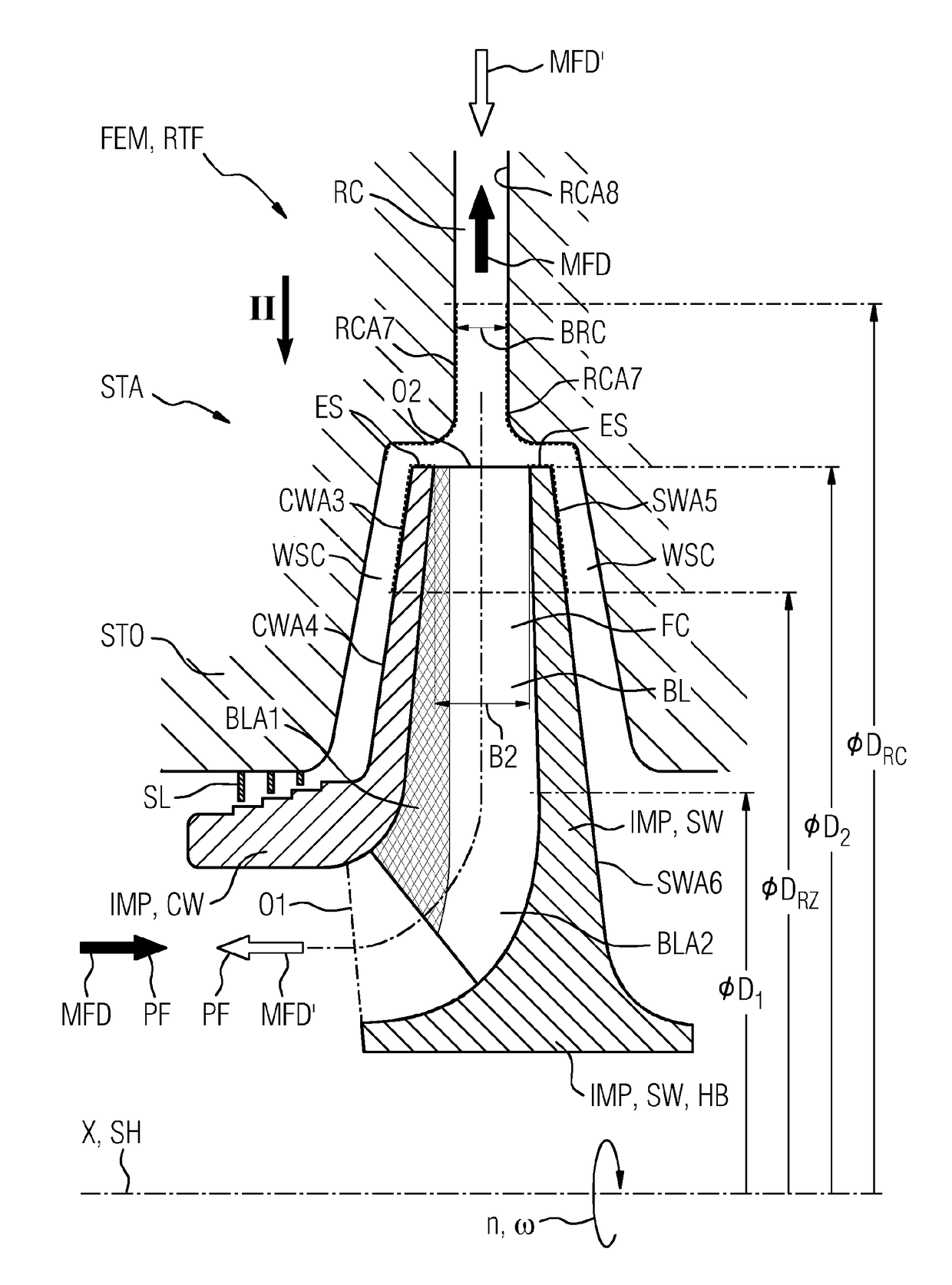
[0019]FIG. 1 shows an impeller IMP of a radial turbo fluid energy machine RTF, which is schematically represented here by way of a detail with one stage STA. A process fluid PF flows along a main flow direction MFD through the impeller IMP when the latter is operating as a compressor. If the impeller IMP is used in a radial turbo fluid energy machine designed as a turbine, the process fluid PF flows along a main flow direction MFD′ that is oriented counter to the main flow direction MFD for the compressor. If, in the following, reference is made to a specific main flow direction MFD, MFD′, this is done with reference to a design of the radial turbo fluid energy machine RTF as a compressor, without restricting the invention to a compressor.

[0020]The impeller IMP comprises a wheel disk SW, blades BL and a cover disk CW, wherein the wheel disk SW comprises a hub HB. By means of the hub HB, the impeller IMP is mounted on a shaft SH (not shown) which extends along a rotation axis X. Unle...


PUM


Abstract

A method for creating an impeller and an impeller of a radial turbo fluid energy machine includes a wheel disc, cover disc, blades, and hub. The hub is mounted on a shaft which extends along an axis, the wheel disc extends substantially radially from the hub, and the cover disc is connected to the wheel disc by the blades such that flow channels separated from one another in the circumferential direction are defined by the blades. The impeller has a first flow passage in a substantially axial direction in the radial proximity of the hub, and the impeller has a second flow passage in a substantially radial direction radially farther away from the hub than the first flow path passage. The cover disc surface facing the wheel disc has a lower degree of roughness at least in some regions than the wheel disc surface facing the cover disc.

Description

CROSS REFERENCE TO RELATED APPLICATIONS[0001]This application is the US National Stage of International Application No. PCT / EP2015 / 074293 filed Oct. 21, 2015, and claims the benefit thereof. The International Application claims the benefit of German Application No. DE 102014222877.8 filed Nov. 10, 2014. All of the applications are incorporated by reference herein in their entirety.FIELD OF INVENTION[0002]The invention relates to a method for creating an impeller of a radial turbo fluid energy machine, and to an impeller comprising: a wheel disk, a cover disk, blades and a hub. In this case, the hub is designed to be mounted on a shaft which extends along an axis, wherein the wheel disk extends essentially radially from the hub, wherein the cover disk is connected to the wheel disk by means of the blades such that flow channels which are separated from one another in the circumferential direction are defined by the blades between the wheel disk and the cover disk in the circumferenti...

Claims


Application Information

Patent Timeline
Patent Type & Authority Applications(United States)
IPC IPC(8): F04D29/68F01D5/04F04D29/30F04D29/44F04D29/28
CPCF04D29/681F04D29/284F01D5/048F05D2230/50F04D29/441F05D2300/516F05D2240/31F04D29/30F04D29/02F04D29/2272
Inventor JONEN, WERNER
Owner SIEMENS AG
Why Eureka
Try Eureka