Diode having high brightness and method thereof

a diode and high brightness technology, applied in the field of diodes, can solve the problems of reducing the brightness of leds, reducing the efficiency of light extraction, and high manufacturing costs, and achieve the effect of high brightness

Inactive Publication Date: 2006-06-27
SUZHOU LEKIN SEMICON CO LTD +1
View PDF25 Cites 65 Cited by
  • Summary
  • Abstract
  • Description
  • Claims
  • Application Information

AI Technical Summary

Benefits of technology

[0012]An advantage of the present invention is providing a diode having high brightness.
[0020]In another aspect, a method of making a light emitting diode having a transparent substrate comprises forming an n-GaN layer having a first doping concentration on a first side of the transparent substrate; forming an InGaN active layer on the n-GaN layer, the active layer having an In concentration in a first range; forming a p-GaN layer having a second doping concentration on the InGaN active layer; forming a p-type contact layer on the p-GaN layer; forming an n-type contact layer on the n-GaN layer by etching the p-type contact layer, p-GaN layer and the InGaN active layer; reducing a thickness of the transparent substrate by backside lapping at a second surface of the transparent substrate; reducing a surface roughness of the transparent substrate; and forming a reflective layer on a reduced surface of the transparent substrate.

Problems solved by technology

In other applications such as general room lighting, manufacturing costs are still much too high, and a simple economy of scale reveals that such devices are not yet the solution.
This photon absorption decreases the light extraction efficiency resulting in reduced brightness of the LED.
Hence, in the manufacturing point of view, it is more difficult to improve optical light output of the LED devices by such growth technique.
However, thus far, these attempts have not led to the level of efficiency and brightness desired from the diode.
Moreover, existing designs require high manufacturing cost.

Method used


Image

  • Diode having high brightness and method thereof
  • Diode having high brightness and method thereof
  • Diode having high brightness and method thereof

Examples


Embodiment Construction

[0030]Reference will now be made in detail to the present invention, examples of which are illustrated in the accompanying drawings.

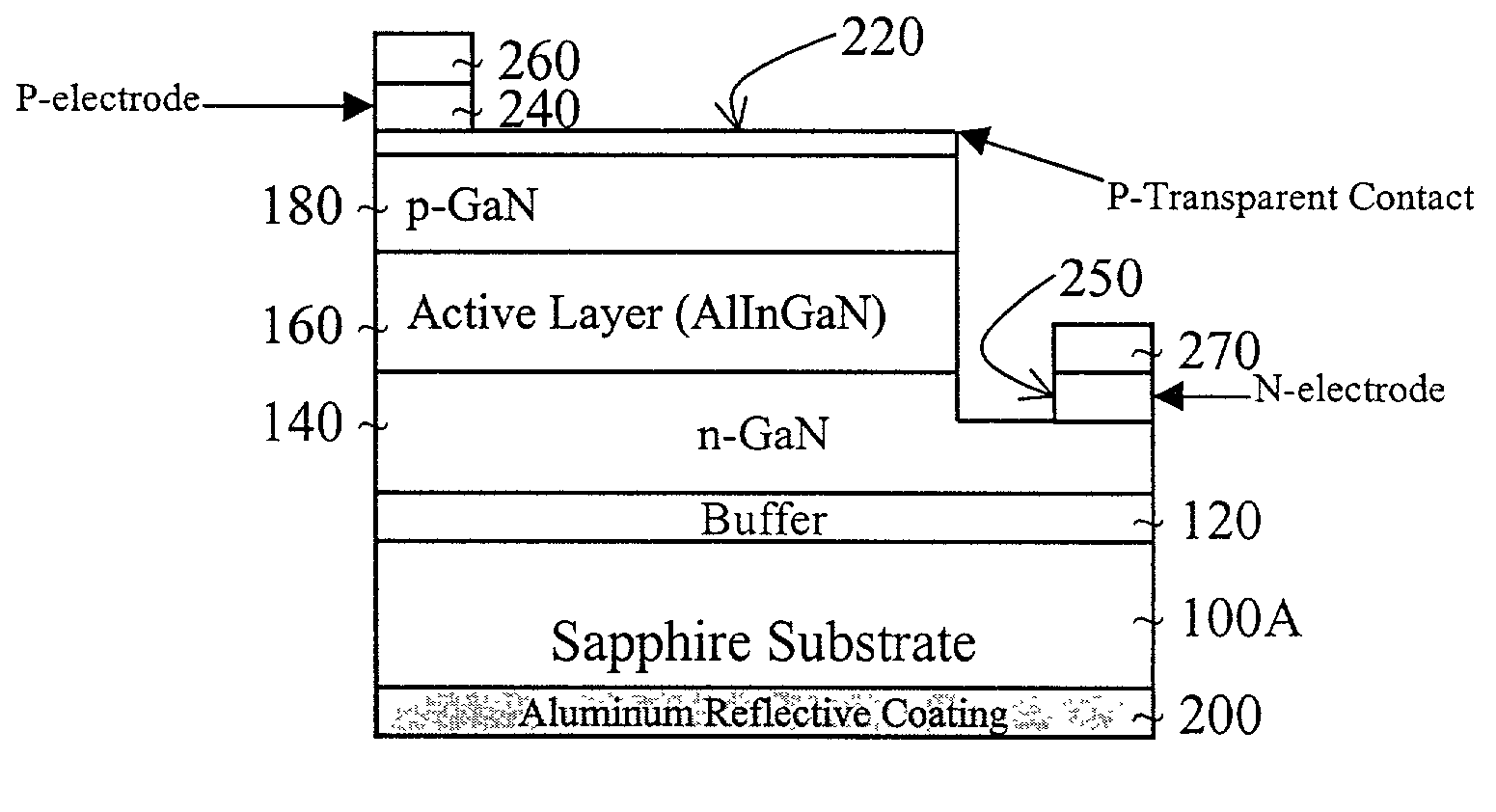
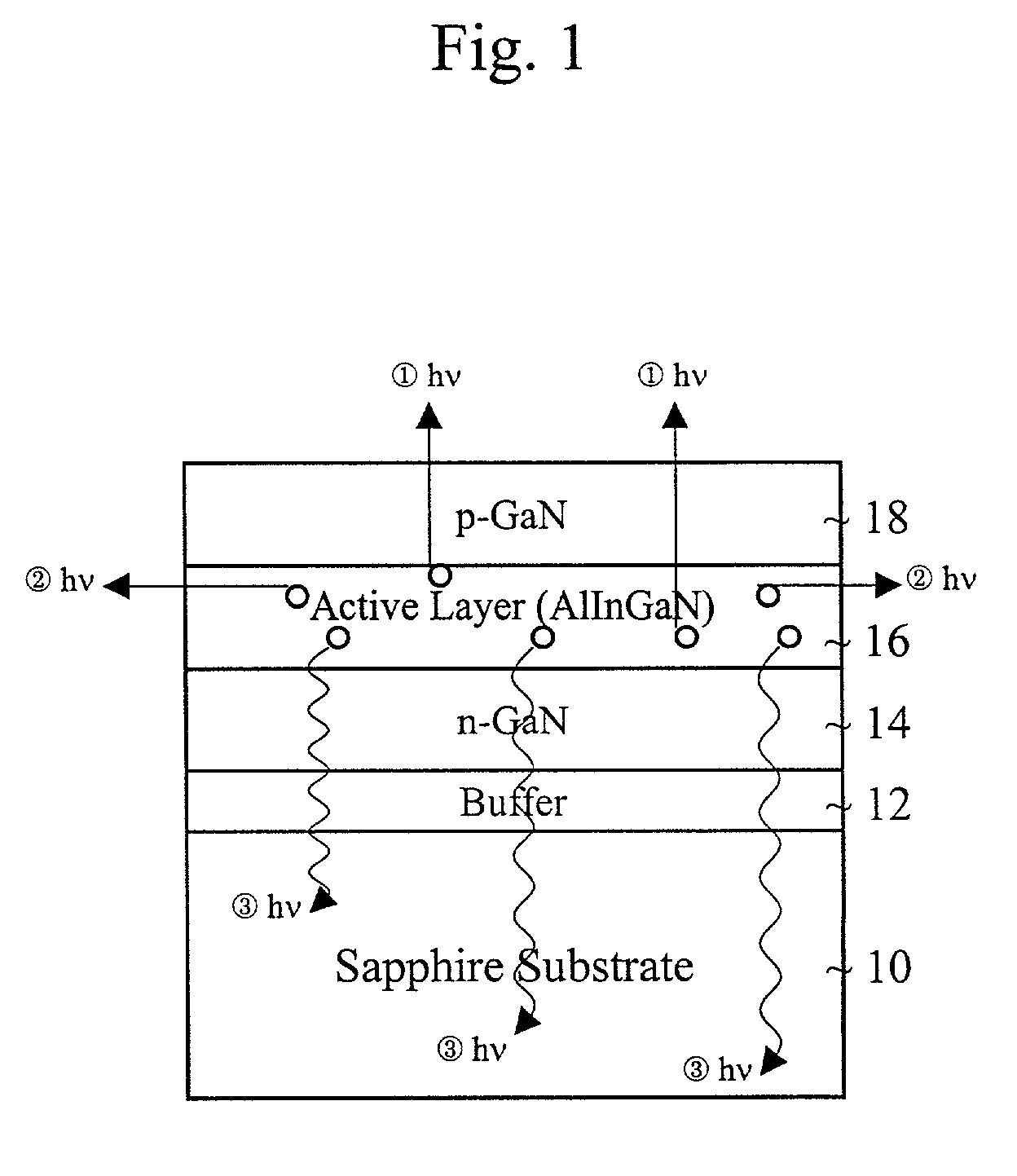
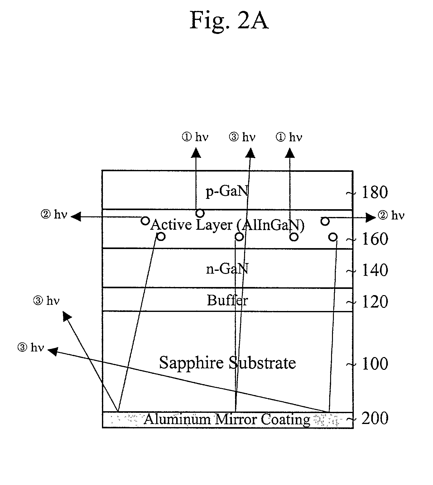
[0031]In order to fabricate GaN-based light emitting diodes (LEDs), sapphire substrate has been generally used since sapphire is very stable and relatively cheaper. The epitaxial layer quality of the AlInGaN grown on sapphire substrate is superior to the other substrate material due to their thermal stability and the same crystal structure of the GaN. However, there are some disadvantages in using sapphire as a substrate material for AlInGAN-based LED device fabrication. Because the sapphire is insulator, forming an n-type bottom contact is not possible. In addition, it is very difficult to perform the post fabrication processes that include the grinding, the polishing, and the scribing since sapphire is almost as hard as diamond. However, transparent sapphire substrate is beneficial for the light extraction compare to the other non-transparent compound...


PUM


Abstract

A light emitting diode includes a transparent substrate and a GaN buffer layer on the transparent substrate. An n-GaN layer is formed on the buffer layer. An active layer is formed on the n-GaN layer. A p-GaN layer is formed on the active layer. A p-electrode is formed on the p-GaN layer and an n-electrode is formed on the n-GaN layer. A reflective layer is formed on a second side of the transparent substrate. Also, a cladding layer of AlGaN is between the p-GaN layer and the active layer.

Description

BACKGROUND OF THE INVENTION[0001]1. Field of the Invention[0002]The present invention relates to diodes, and more particularly, to light emitting diodes (LEDs). Although the present invention is discussed with reference to light emitting diodes, the present invention can be used in a wide range of applications including, for example, other types of diodes such as laser diodes.[0003]2. Discussion of the Related Art[0004]Gallium-Nitride (GaN) based opto-electronic device technology has rapidly evolved from the realm of device research and development to commercial reality. Since they have been introduced in the market in 1994, GaN-based opto-electronic devices have been considered one of the most promising semiconductor devices. The efficiency of GaN light emitting diodes (LEDs), for example, has surpassed that of incandescent lighting, and is now comparable with that of fluorescent lighting.[0005]The market growth for GaN based devices has been far exceeding than the industrial marke...

Claims


Application Information

Patent Timeline
Patent Type & Authority Patents(United States)
IPC IPC(8): H01L33/00H01L33/32H01L33/46
CPCH01L33/46H01L33/32H01L33/0025H01L33/06H01L33/42H01L33/387H01L33/483H01L33/22H01L33/12H01L25/0753H01L33/405H01L33/62
Inventor YOO, MYUNG CHEOL
Owner SUZHOU LEKIN SEMICON CO LTD
Why Eureka
Try Eureka