Rotor for a turbo machine

a technology for turbo machines and rotors, which is applied in the direction of climate sustainability, leakage prevention, air transportation, etc., can solve the problems of reducing the service life of the rotor, reducing requiring a relatively large radial structural space, so as to improve the rigidity of the rotor, improve the service life, and improve the service life.

Inactive Publication Date: 2012-05-17
MTU AERO ENGINES GMBH
View PDF4 Cites 2 Cited by
  • Summary
  • Abstract
  • Description
  • Claims
  • Application Information

AI Technical Summary

Benefits of technology

[0013]Further advantages result if the second angle is between 2° and 80°, in particular between 10° and 20° An angle between 2° and 80° in this case is understood to be, in particular, 2°, 4°, 6°, 8°, 10°, 12°, 14°, 16°, 18°, 20°, 22°, 24°, 26°, 28°, 30°, 32°, 34°, 36°, 38°, 40°, 42°, 44°, 46°, 48°, 50°, 52°, 54°, 56°, 58°, 60°, 62°, 64°, 66°, 68°, 70°, 72°, 74°, 76°, 78° or 80°, as well as corresponding intermediate angles. A particularly good introduction of cooling air and/or a particularly high strain relief of the rotor and rotating blade regions lying radially above the channel is possible when the second angle is 10°, 11°, 12°, 13°, 14°, 15°, 16°, 17°, 18°, 19° or 20°. The second angle here can also be determined basically in the counter-clockwise or in the clockwise direction, i.e., it can be formally positive (e.g.)+15° or negative (e.g.) −15°.
[0014]In another advantageous embodiment of the invention, it is provided that the channel is designed as a relief borehole and/or as a cooling air channel. As a relief borehole, the channel produces a tangential interruption of the rotor, by which means the rotor regions lying radially above the channel are relieved of strain. If the channel is designed alternatively or additionally as a cooling air channel, it may be provided that the channel is fluidically coupled with inner cooling channels of the rotating blade, so that cooling air can enter through the channel into the rotating blade.
[0015]In another advantageous embodiment of the invention, it is provided that the rotor is joined to the drum radially below the channel. In this way, the rigidity of the drum (so-named “drum”) can be utilized in order to increase the rigidity of the rotor, by which means a particularly advantageous vibration behavior, in particular with respect to coupling vibrations of basic rotor body and rotating blades is achieved. In addition to a construction that is lighter in weight with a simultaneously more rigid total system, a shorter radial construction of stators of an associated turbo machine is also made possible in this way, since the drum can be radially disposed near the gas channel. One can therefore advantageously dispense with large and voluminous sealing elements—for example, so-called honeycombs, labyrinth seals or the like. In this case, t

Problems solved by technology

This adversely affects the mechanical properties of the rotor and reduces its service life.
Viewed as a disadvantage in the known rotor is thus the circumstance that this rotor requires a relatively large radial

Method used


Image

  • Rotor for a turbo machine
  • Rotor for a turbo machine
  • Rotor for a turbo machine

Examples


Embodiment Construction

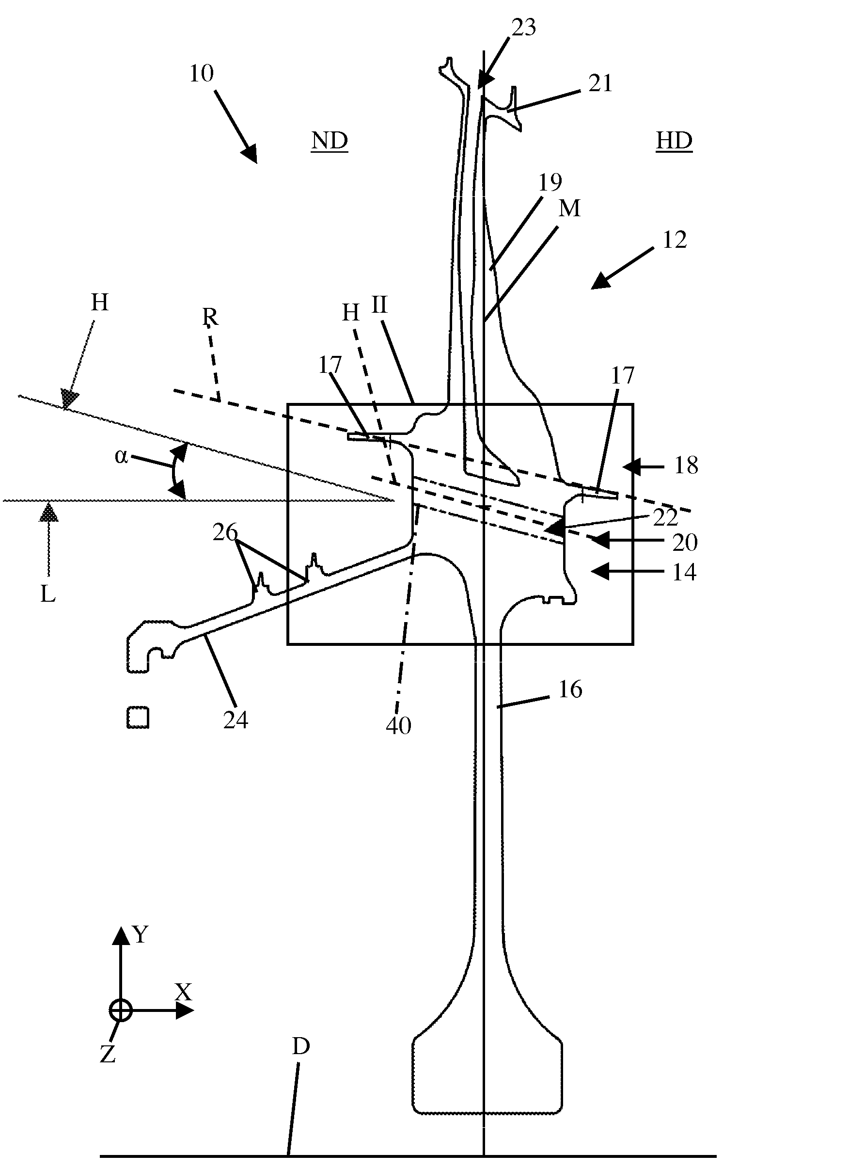
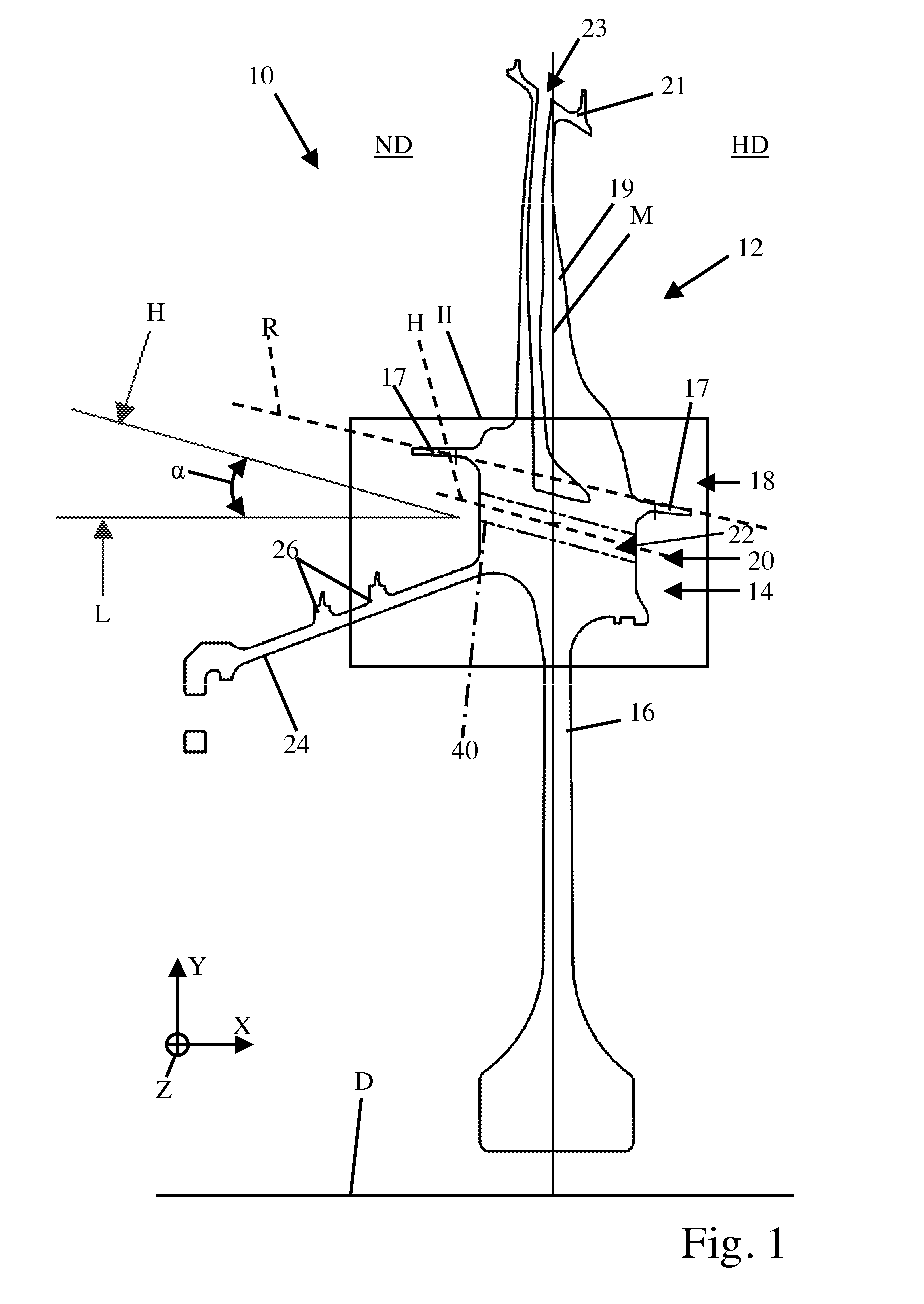
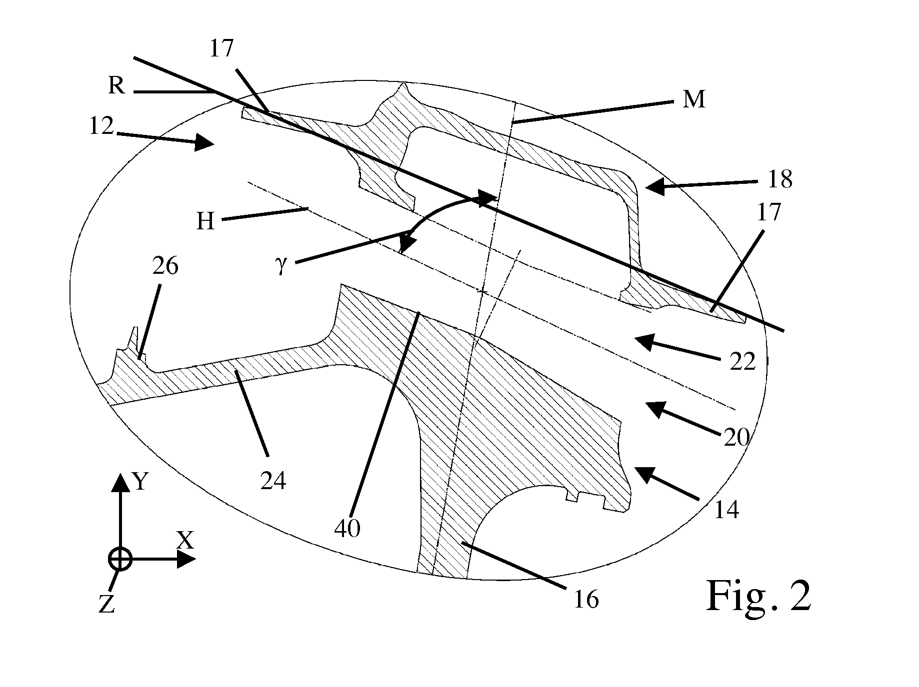
[0026]FIG. 1 shows a schematic lateral sectional view of a rotor 10 according to the invention for an aircraft turbine (not illustrated) and will be explained together with FIG. 2 in the following, and FIG. 2 shows an enlarged representation of the detail II shown in FIG. 1. A rotor 10, which is formed presently as a so-called BLISK, comprises several rotating blades 12. Each rotating blade 12 is joined cohesively to a basic rotor body 16 via its blade foot 14. Between a blade platform 18 and the blade foot 14, rotating blade 12 has a channel 22 extending between the high-pressure side HD and the low-pressure side ND of rotor 10 in the region of its blade neck 20. The underside of channel 22 in this case defines the radially outer edge 40 of the solid, uninterrupted rotor disk 16, in which this edge 40 is also designated a “life rim”. In the present example of embodiment, rotor 10 has one channel 22 per rotating blade 12. Basically, however, more or fewer channels 22 than rotating b...


PUM

PropertyMeasurementUnit
Angleaaaaaaaaaa
Angleaaaaaaaaaa
Angleaaaaaaaaaa

Abstract

The invention relates to a rotor (10) for a turbo machine, in particular for an aircraft turbine, with rotating blades (12) that are joined to a basic rotor body (16), whereby at least one channel (22) extending between the high-pressure side (HD) and the low-pressure side (ND) of rotor (10) radially underneath a blade platform (18) of at least one rotating blade (12) is provided, whereby a slope of a principal axis of extension (H) of channel (22) relative to an axis of rotation (D) of rotor (10) has the same sign as a slope of a principal axis of extension (R) of a radially inner boundary of the flow channel of rotor 10. In addition, the invention relates to a turbo machine having a rotor (10) as well as to a method for manufacturing a rotor (10) for a turbo machine.

Description

BACKGROUND OF THE INVENTION[0001]The invention relates to a rotor of the type indicated in the preamble of patent claim 1, a turbo machine with a rotor, as well as a method for manufacturing a rotor for a turbo machine.[0002]In turbo machines, such as aircraft turbines, for example, which are used in a number of variants in aircraft, but also in different types of aircraft and in stationary applications, continually higher temperatures in internal combustion chamber(s) are targeted in order to obtain an improved efficiency. In the high-pressure part of the aircraft turbine that is connected downstream of the internal combustion chamber, all open surfaces of guide vanes and rotating blades as well as of other components that lay open are therefore subjected to temperatures that can lie partially in the region of the melting point of the materials used. In order to be able to operate an aircraft turbine at a temperature that is as high as possible, the components and particularly the ...

Claims


Application Information

Patent Timeline
IPC IPC(8): F01D5/18B23P15/04
CPCF01D5/22F01D11/006F04D29/321F04D29/668Y10T29/49318Y02T50/673Y02T50/676F01D5/187Y10T29/49321Y02T50/671Y02T50/60
Inventor BORUFKA, HANS PETERSTIEHLER, FRANK
Owner MTU AERO ENGINES GMBH
Why Eureka
Try Eureka